


- 1
- 2
- 3
- 4
CST同轴线器件的仿真设计分析―CST2013设计实例
Common Solver Settings
To this point, only the structure itself has been modeled. Now it is necessary to define some solver-specific elements. For an S-parameter calculation, you need to define input and output ports. Additionally, the simulation needs to know how the calculation domain should be terminated at its bounds.
Define Ports
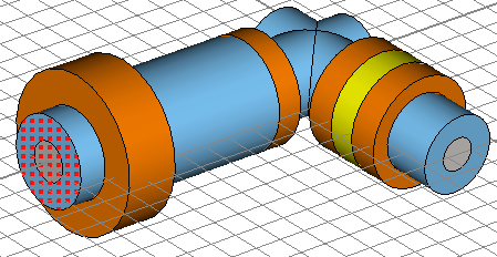
Each port that is defined will simulate an infinitely long waveguide (here a coaxial cable) that is connected to the structure at the ports plane. Waveguide ports are the most accurate way to calculate the S-Parameters of filters and should therefore be used in this case.
Since a waveguide port is based on the two dimensional mode patterns in the waveguides cross-section, the port must be defined large enough to entirely cover these mode fields. In the case of a coaxial cable, the port has to completely cover the coaxial cables substrate.
Before you continue with the port definition, please clear the selection by either double-clicking on the views background or selecting Components in the navigation tree.
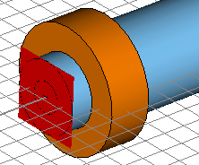
The ports extent can be defined either numerically or, as is more convenient here, by picking the face to be covered by the port. Therefore, activate the general pick tool (Modeling: Picks > Picks > Pick Point, Edge or Face (S)) and double-click the substrates port face at the first port as shown in the picture below:
Please open the waveguide dialog box (Simulation: Sources and Loads > Waveguide Port ) to define the first port 1:
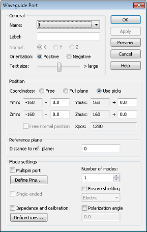
Whenever a face is picked before the port dialog is opened, the ports location and size will automatically be defined by the picked faces extent. Thus the ports Position (transversal as well as normal) is initially set to Use picks. You can accept this setting. The next step is to choose how many modes should be considered by the port. For coaxial devices, we usually have only a single propagating mode. Therefore, you should simply keep the default of one mode.
Finally, check the settings in the dialog box and press the OK button to create the port:
Now you can repeat the same steps for the definition of the second port:
1. Pick the corresponding substrates port face (Modeling: Picks Picks Pick Point, Edge or Face (S)).
2. Open the waveguide dialog box (Simulation: Sources and Loads Waveguide Port .)
3. Press OK to store the ports settings.
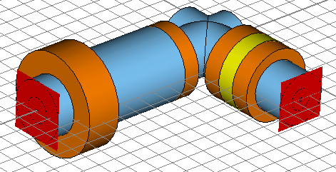
Your model including the ports should now look as follows:
-
CST中文视频教程,资深专家讲解,视频操作演示,从基础讲起,循序渐进,并结合最新工程案例,帮您快速学习掌握CST的设计应用...【详细介绍】
推荐课程

-

7套中文视频教程,2本教材,样样经典
-

国内最权威、经典的ADS培训教程套装
-

最全面的微波射频仿真设计培训合集
-

首套Ansoft Designer中文培训教材
-
矢网,频谱仪,信号源...,样样精通
-

与业界连接紧密的课程,学以致用...
-

业界大牛Les Besser的培训课程...
-

Allegro,PADS,PCB设计,其实很简单..
-

Hyperlynx,SIwave,助你解决SI问题
-

现场讲授,实时交流,工作学习两不误
