


- 1
- 2
- 3
- 4
CST同轴线器件的仿真设计分析―CST2013设计实例
Afterwards you need to select the previously picked face once again (Modeling: Picks > Picks > Pick Point, Edge or Face (S) + double-click on the face). Activate the rotate face mode by selecting Modeling: Shapes > Extrusions Rotate . Because a face has been previously picked, the definition of polygon points is skipped and a dialog box is opened immediately:
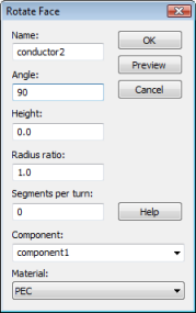
In this dialog box, you should first assign a proper Name (e.g. conductor2) to the shape. Because the rotation axis is aligned with the negative v-axis direction and the rotation angle is specified in a right-handed system, the Angle must be set to 90 degrees (the rotation axis is visualized by a blue arrow while the dialog box is open). If not already set, change the Material assignment to PEC and press the OK button.
The last step in the models geometric construction process is to create the third conductor by extruding the end face of the figure of rotation defined above. Rotate the view to obtain a picture similar to the following:
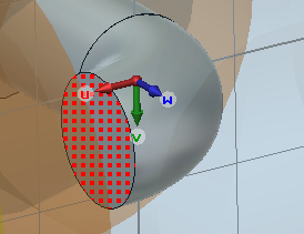
Afterwards, select conductor2 and pick the end face of the conductor as shown in the above picture (Modeling: Picks > Picks > Pick Point, Edge or Face (S) +double-click on the end face).
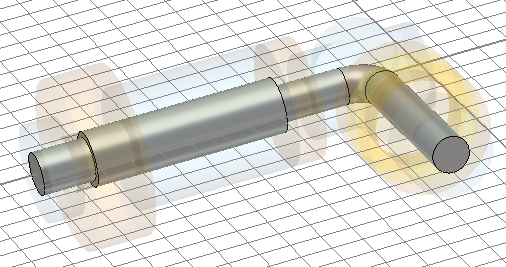
You can now open the Extrude Face dialog box by selecting Modeling: Shapes > Extrude. As with the figure of rotation, a polygon definition mode will be entered by the extrude tool if no face has been previously selected.
In this dialog box, please assign a proper Name (e.g. conductor3), set the Height to 600 (mil) and the Material assignment to PEC before pressing the OK button. Your structure should then look as follows:
-
CST中文视频教程,资深专家讲解,视频操作演示,从基础讲起,循序渐进,并结合最新工程案例,帮您快速学习掌握CST的设计应用...【详细介绍】
推荐课程

-

7套中文视频教程,2本教材,样样经典
-

国内最权威、经典的ADS培训教程套装
-

最全面的微波射频仿真设计培训合集
-

首套Ansoft Designer中文培训教材
-
矢网,频谱仪,信号源...,样样精通
-

与业界连接紧密的课程,学以致用...
-

业界大牛Les Besser的培训课程...
-

Allegro,PADS,PCB设计,其实很简单..
-

Hyperlynx,SIwave,助你解决SI问题
-

现场讲授,实时交流,工作学习两不误
