


- 1
- 2
- 3
- 4
CST同轴线器件的仿真设计分析―CST2013设计实例
Model the Teflon and Rubber Cylinders
After successfully modeling the air parts, you can now create the first Teflon cylinder. Again it is advantageous to move the WCS to the middle of the Teflon cylinder by selecting Modeling: WCS > Transform WCS and enter the expression 390 + 310 / 2 in the DW field to move the WCS along the w-axis by this amount. Please refer to the structures schematic drawing earlier in this tutorial to confirm that the new origin of the WCS is located in the center of the first Teflon cylinder.
Once the coordinate system is properly located, you can now easily model the Teflon cylinder by selecting Modeling: Shapes > Cylinder . When you are requested to enter the cylinders center, press Shift+Tab and check the coordinate values U=0, V=0 before clicking the OK button.
Afterwards, press the Tab key again to set the cylinders outer radius to 200. The height of the cylinder should then be set to 310 / 2 (you are currently modeling only one half of the cylinder) in the same way. After skipping the definition of the inner radius by pressing the Esc key, the cylinder creation dialog box should appear, where you should assign a proper Name (e.g. teflon1) to the shape before you also enter the expression "-310/2" in the Wmin field to properly set the cylinders full length:
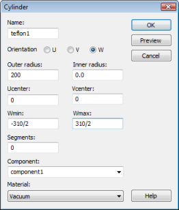
You can skip the Component setting because the complete connector will be constructed as one component. However, the cylinders material is currently set to Vacuum. In order to change this, select [New material...] in the Material dropdown list, opening the material parameter dialog box:
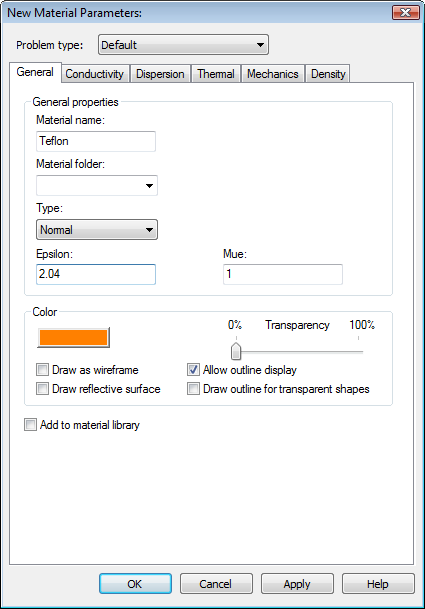
In this dialog box you should set the Material name to Teflon and the Type to be a Normal dielectric material. Afterwards, you can specify the dielectric constant of Teflon by entering 2.04 in the Epsilon field. Select the Change button in the Color frame and choose a color.
Finally, you should check your settings in the dialog box again before pressing the OK button to store the materials parameters.
Please note: The defined material Teflon will now be available inside the current project for the further creation of other solids. However, if you also want to save this specific material definition for other projects, you may check the button Add to material library. You will have access to this material database by clicking on Load from Material Library in the Materials context menu in the navigation tree.
The dialog for the cylinder creation should now look as follows:

After checking the current settings, create the cylinder by pressing the OK button. Since the Teflon cylinder overlaps the previously modeled air parts, the shape intersection dialog box will appear again:
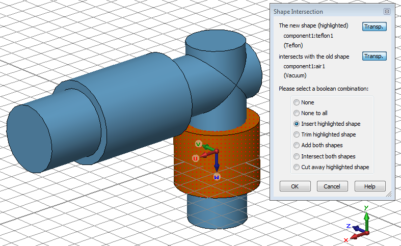
Here, you should choose to insert the new Teflon cylinder into the air part by selecting Insert highlighted shape before pressing the OK button. Please refer to the CST STUDIO SUITE Getting Started manual for more information on Boolean operations.
Afterwards, the rubber ring inside the first Teflon cylinder can be modeled analogously:
1. Activate the cylinder creation tool (Modeling: Shapes Cylinder ).
2. Press Shift+Tab and set the center point to U = 0, V = 0.
3. Press Tab and set the Radius to 200.
4. Press Tab and set the Height to 100/2.
5. Press Tab and set the inner Radius to 140.
6. Set the Name to rubber and enter -100/2 in the Wmin field.
7. Select [New Material...] from the Material dropdown list to create a new material.
8. In the material properties dialog box set the Material name to Rubber, its Type to Normal and its dielectric constant Epsilon to 2.75.
9. Choose a color by pressing the Change button and confirm the material creation by pressing OK.
10. Back in the cylinder creation dialog box, verify the material assignment to Rubber and press the OK button.
11. In the shape intersection dialog box, choose Insert highlighted shape and press OK.
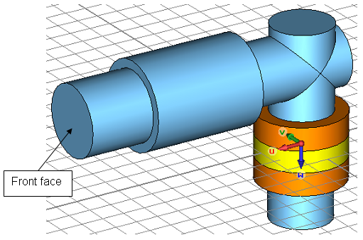
After successfully performing all above steps, your model should look as follows:
-
CST中文视频教程,资深专家讲解,视频操作演示,从基础讲起,循序渐进,并结合最新工程案例,帮您快速学习掌握CST的设计应用...【详细介绍】
推荐课程

-

7套中文视频教程,2本教材,样样经典
-

国内最权威、经典的ADS培训教程套装
-

最全面的微波射频仿真设计培训合集
-

首套Ansoft Designer中文培训教材
-
矢网,频谱仪,信号源...,样样精通
-

与业界连接紧密的课程,学以致用...
-

业界大牛Les Besser的培训课程...
-

Allegro,PADS,PCB设计,其实很简单..
-

Hyperlynx,SIwave,助你解决SI问题
-

现场讲授,实时交流,工作学习两不误
