Topology - Routes
Edit Cabling  Create Route
  Route from Curve
As a prerequisite for this function a curve has to be assigned first.
A new curve can be defined by
Curves  New
Curve (see Curve
Creation). The Route from Curve
function allows to select a predefined curve by using the mouse pointer
inside the Main View. After the curve has been
selected a small dialog box prompts the user to define a name for the
Route. By pressing the OK button the curve will be transformed into a
trace of a new Route.
Edit Cabling  Create Route
  Route from Selected Nodes
This feature prompts the user to select a sequence of existing nodes
by using the mouse pointer inside the Main View. The sequence of the nodes
determine the trace of the new
Route.
Edit Cabling  Create Route
  Route from Start and End Nodes
This feature prompts the user to select a starting and an end node
for the new Route. The program automatically tries to build a new Route
by searching a trace through
already existing segments.
Edit Cabling  Routes and Laying
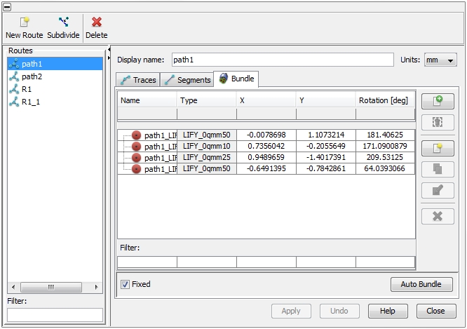
The Edit Routes dialog box
combines two different functions: the definition of the
traces and the placing of cables
inside the Route. On the left side of the dialog box all predefined Routes
are listed. On the right side the specific settings of the selected Route
can be seen. The dialog box can be also accessed
via Cable Navigation Tree:
Routes: selecting
the Routes folder and either
double-clicking or choosing Edit inside the context menu
(via right-mouse-click). The icons on the top of the dialog box
enable actions which are explained below. The meaning of each icon is
also explained by tool-tips. To see a tool-tip just move the mouse-pointer
over the corresponding icon:
 Subdivide all segments which belong to the selected
route
 Delete selected routes
Traces
tab
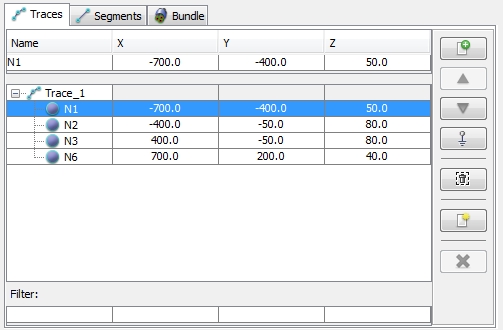
A Trace is a sequence of Nodes which determine the path of the corresponding
Route in the 3D space. The Node sequence of all traces are displayed with
the help of a table. The coordinates of the listed Nodes can be edited.
The icons on the right side enable actions which are explained below.
The meaning of each icon is also explained by tool-tips. To see a tool-tip
just move the mouse-pointer over the corresponding icon:
 Add a new (predefined) node to the trace
 Move a node upwards in the list
 Move a node downwards in the list
 Remove a node from in the list
 Delete a selected trace
Segments
tab
This tab lists all segments the Route does consist of. The
icons on the right side enable actions which are explained below. The
meaning of each icon is also explained by tool-tips. To see a tool-tip
just move the mouse-pointer over the corresponding icon:
 Add a new segment to the list. Opens a dialog box
where the user can select a predefined but still unused segment (see Adding a stub to a Route).
 Edit the selected segment. Opens the Edit
Segment dialog box.
 Subdivide the selected segment. Opens the Subdivide
Segment dialog box.
This tab lists all cables which are assigned to the Route. The icons
on the right side enable actions which are explained below. The meaning
of each icon is also explained by tool-tips. To see a tool-tip just move
the mouse-pointer over the corresponding icon:
 Add a new cable.
The user can choose from all cables defined in the Cable
Library. An added cable will be automatically assigned with a unique
name in order to distinguish it from other cables (see first column of
Bundle tab below). The name is generally composed by <route
name>_<cable type>_<index>. The user can change the
name by selecting the corresponding row in the table cable and editing
the cell in the Name column. All
cables inside the list are assigned to the Route and to its related Segments. The latter is of special importance
since Segments may be shared by more than one Route. If anything changes
in one of the Routes it has to be updated immediately for each Segment.
If there are any potential problems or mismatching the user will be immediately
informed.
 Duplicate a cable in the bundle
 Remove a cable from in the list
 Edit insulator of sub-bundle.
Definition of an additional insulating material, which e.g. can
be wrapped around the sub-bundle (see also Bundle
in segment)
 Delete a selected sub-bundle
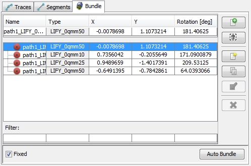
When putting a new cable to the bundle it will be positioned in the
origin point and without any additional measures the cable will overlap
with the existing ones. On the left bottom side there is the Fixed check button as shown in the figure
above. As long as this button is not activated, the user doesn't have
to care about an overlap, since the program will automatically remove
all overlaps after the Meshing
and Modeling procedure has
been started. The disadvantage of this automated repair is the missing
control on the cable positions. If the button is activatd the user has
to care about removing the overlaps in the corresponding segment. There
are two options for re-arranging the cables:
Manually by editing the coordinates in
the table.
Pressing the Auto
Bundle button on the right bottom of the dialog box.
The effect of the re-arranging is shown in the two figures below:
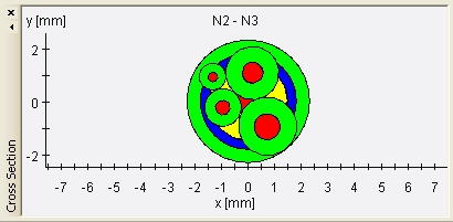
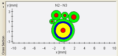
Before re-arranging:
overlapping segments After re-arranging: no overlapping segments
If the user decides for an active positioning of the cables (either
by inserting the positions manually or by pressing the Auto
Bundle) the Fixed check
box will be activated automatically. This is because in case of an de-activated
Fixed button, following meshing procedure will change the positions
automatically. If the user wants to undo the editing
he can press the Undo button as
long as the Apply button has not
been pressed yet.
Create a new Route 
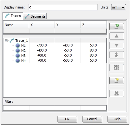
The Create New Route dialog
box allows the definition of the Route in two different way - either by
defining a Traces or by defining
a list of Segments.
Define a Route by Traces
The icons on right side of the Traces
tab enable actions which are explained below. The meaning of each icon
is also explained by tool-tips. To see a tool-tip just move the mouse-pointer
over the corresponding icon (see Traces tab):
 Add a new (predefined) node to the trace
 Move a node upwards in the list
 Move a node downwards in the list
 Remove a node from in the list
 Delete a selected trace
Define a Route by Segments
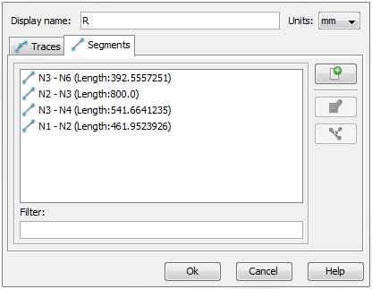
The icons on right side of the Segments
tab enable actions which are explained below. The meaning of each icon
is also explained by tool-tips. To see a tool-tip just move the mouse-pointer
over the corresponding icon (see Segments tab):
 Add a new segment to the list. Opens a dialog box
where the user can select a predefined but still unused segment (see Adding a stub to a Route).
 Edit the selected segment. Opens the Edit
Segment dialog box.
 Subdivide the selected segment. Opens the Subdivide
Segment dialog box.
Adding a stub to a Route
Sometimes a stub is necessary to transport a certain signal not only
from one point to another point but to deliver the signal to a third point.
This can be done by inserting a stub
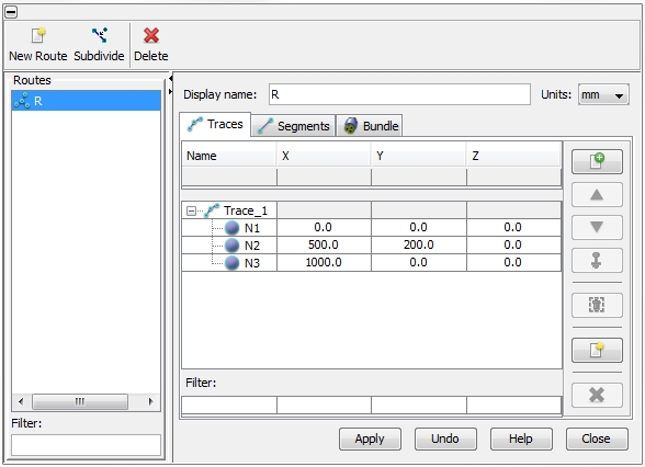
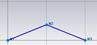
trace on an already existing trace. The figure below shows the
definition of a route consisting of a trace with three nodes:
The corresponding Route is
shown in the figure below:
Next a stub trace shall be made from Node N2
to a new node N4. Therefore,
we select the Traces
tab and press the New
Trace button on the right side  . A new row including
the name Trace_2 will be added.
We select this trace and press the Add
Node button on the right side  . The Node
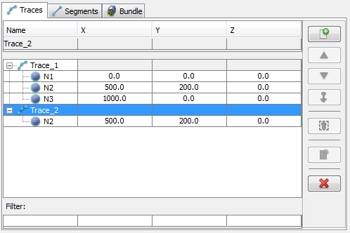
Definition dialog box appears prompting us to select the anchor
node where the new stub trace shall start from. This strong rule
prevents the user from defining unconnected stubs. We select node N2 and press Ok.
The corresponding Trace tab looks
like in the figure below:
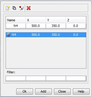
Again we press the Add Node
button  and we define node N4
in the Node Definition dialog box as shown in
the figure below:
Now the Trace tab looks like
in the figure below:
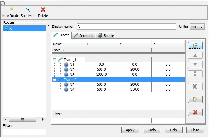
After pressing the Apply button
the Route is updated by a stub trace as shown in the figure below:
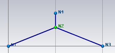
We see the additional node N4
and we also recognize the color of N2
has been changed. This color change indicates that
node N2 has converted in a so
called Splice Node. At a Splice Node a signal deviates in two
or even more directions. The different color can be defined in the View
Harness Attributes dialog box.
Defining
connection to metallic environment
In case of a uni- or bi-directional cable-to-field coupled
simulation (see Field Coupled
Workflows), every End-Node
of a Route has to be specified whether a galvanic connection between its
terminals (see Cabling, Signals
and Terminals) and the next point onto the surrounding metallic structure
should be enabled or not (see Closed
current loop in 3D field domain).
In order to define the possible connections the user must change into
the Traces tab and press the
button with the ground symbol  (see Traces tab).
The button is released only if any metallic structure is defined in the
3D space . The dialog providing all End-Nodes
of the Route is shown in the figure below
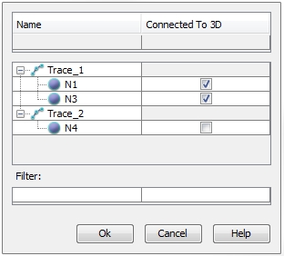
The nodes N1 and N3
shall be prepared to allow a galvanic connection to the metallic environment.
After pressing Ok the color of
N1 and N3
changes to yellow as shown in the figure below. This indicates that a
current from the cable can flow onto the next closest point on the metallic
environment:
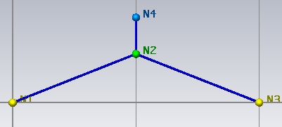
Note:
The yellow nodes only visualize that a galvanic
connection between the corresponding terminals of the nodes and the metallic
environment is possible. If such
a galvanic connection really exists is defined via the schematic editor
(see Field Coupled Workflows).
Declaring a Node to be connected to 3D does only
make sense if the distance of
this Node to the next point on
its surrounding metallic structure is small compared to the smallest wavelength
which is expected for the coupled cable-to-circuit simulation. If this
pre-requisite is not true a warning will be dropped during the circuit
simulation run.


 Create Route
  Route from Curve
 New
Curve (see Curve
Creation). The Route from Curve
function allows to select a predefined curve by using the mouse pointer
inside the Main View. After the curve has been
selected a small dialog box prompts the user to define a name for the
Route. By pressing the OK button the curve will be transformed into a
trace of a new Route.
 Create Route
  Route from Selected Nodes
 Create Route
  Route from Start and End Nodes
 Routes and Laying
  Create a new route
 Subdivide all segments which belong to the selected
route
 Delete selected routes
 Add a new (predefined) node to the trace
 Move a node upwards in the list
 Move a node downwards in the list
 Enable connection to metallic environment in the 3D
space (see Defining
connection to metallic environment)
 Remove a node from in the list
 Create a new trace (see Adding
a stub to a Route)
 Delete a selected trace
 Add a new segment to the list. Opens a dialog box
where the user can select a predefined but still unused segment (see Adding a stub to a Route).
 Edit the selected segment. Opens the Edit
Segment dialog box.
 Subdivide the selected segment. Opens the Subdivide
Segment dialog box.
 Add a new cable.
The user can choose from all cables defined in the Cable
Library. An added cable will be automatically assigned with a unique
name in order to distinguish it from other cables (see first column of
Bundle tab below). The name is generally composed by <route
name>_<cable type>_<index>. The user can change the
name by selecting the corresponding row in the table cable and editing
the cell in the Name column. All
cables inside the list are assigned to the Route and to its related Segments. The latter is of special importance
since Segments may be shared by more than one Route. If anything changes
in one of the Routes it has to be updated immediately for each Segment.
If there are any potential problems or mismatching the user will be immediately
informed.
 Duplicate a cable in the bundle
 Remove a cable from in the list
 Create a sub-bundle
(see also Bundle in segment)
 Edit insulator of sub-bundle.
Definition of an additional insulating material, which e.g. can
be wrapped around the sub-bundle (see also Bundle
in segment)
 Delete a selected sub-bundle


 Add a new (predefined) node to the trace
 Move a node upwards in the list
 Move a node downwards in the list
 Enable connection to metallic environment in the 3D
space (see Defining
connection to metallic environment)
 Remove a node from in the list
 Create a new trace (see Adding
a stub to a Route)
 Delete a selected trace
 Add a new segment to the list. Opens a dialog box
where the user can select a predefined but still unused segment (see Adding a stub to a Route).
 Edit the selected segment. Opens the Edit
Segment dialog box.
 Subdivide the selected segment. Opens the Subdivide
Segment dialog box.


 . A new row including
the name Trace_2 will be added.
 . The Node
Definition dialog box appears prompting us to select the anchor
node where the new stub trace shall start from. This strong rule
prevents the user from defining unconnected stubs. We select node N2 and press Ok.
The corresponding Trace tab looks
like in the figure below:
 and we define node N4
in the Node Definition dialog box as shown in
the figure below:


 (see Traces tab).
The button is released only if any metallic structure is defined in the
3D space . The dialog providing all End-Nodes
of the Route is shown in the figure below
