Topology - Segments
Edit Cabling  Create Segment Create Segment
This feature prompts the user to select two existing nodes by using
the mouse pointer inside the Main View.
Edit Cabling Create Segment Edit Segments
The Edit Segments dialog box
shows two lists: on the left side is the list of all available nodes,
on the right side the list of the existing segments. The dialog box can
be also accessed via Cable Navigation
Tree: Segments:
selecting the Segments folder
and either double-clicking or
choosing Edit inside the context
menu (via right-mouse-click).
The icons on the top of the dialog box enable actions which are explained
below. The meaning of each icon is also explained by tool-tips. To see
a tool-tip just move the mouse-pointer over the corresponding icon:
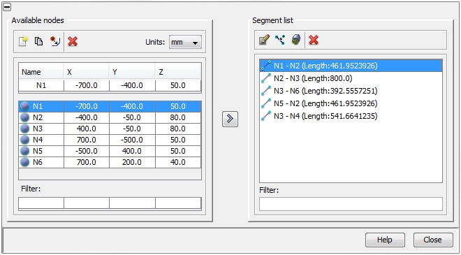
The Available nodes frame in
the left column includes all features to define and edit nodes (see Nodes). The Segment
list frame on the right enables the following actions which are
listed below. The meaning of each icon at top of the frame is also explained
by tool-tips. To see a tool-tip just move the mouse-pointer over the corresponding
icon:
 Bundle all existing segments automatically
 Delete the selected segments
Defining a new segment
Segments are defined by pairs of Nodes. If you select any number of
nodes on the left side the arrow button ">"
will be enabled. You have the following possibilities how to create a
segment:
Select one node on the left side and press the arrow
button ">".
A new segment will be added to the segment list on the right. Now select
a second (different) node and press the arrow button ">" again in order to complete
the segment. Incomplete segments are indicated by dots
Select two nodes on the left side by using the left
mouse button and <CTRL>.
When pressing the arrow button ">"
a new segment in-between these two nodes will be added to the segments
list.
Select an arbitrary number of nodes on the left side.
If you press the arrow button ">",
all nodes will be grouped into pairs in the order of their appearance
in the node list, and a corresponding number of segments will be automatically
created on the right side.
The segment’s length is displayed in parentheses in the specified
unit length that can be defined on the right top of the Available
Nodes - frame.
Editing a segment 
Pressing the button leads to the dialog box as shown in the figure
below. The name of the selected segment is shown on the top. The dialog
box itself consists of two different tabs: Bundle
and Nodes:
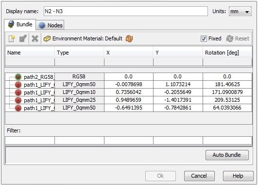
Bundle
tab
The meaning of the Bundle tab
is best explained by using the example from Topology
Overview. The segment includes cables from two different Routes and
without any additional measures these cables will overlap. On the top
right of the bundle tab there is the Fixed
button. If this button is activated the user has to care about removing
the overlaps in the corresponding segment. There are two options for re-arranging
the cables:
Manually by editing the coordinates in
the table.
Pressing the Auto
Bundle button on the right bottom of the dialog box.
The effect of the re-arranging is shown in the two figures below:
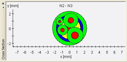
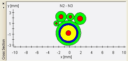
Before re-arranging:
overlapping cables After re-arranging: no overlapping cables
After the re-arranging the Reset
button on the top right of the dialog box is released. By pressing the
button the bundle can be restored to the status before the re-arranging.
If the user de-activates the Fixed
button the CST Cable Studio will remove all overlaps during the Meshing and Modeling
procedure automatically (see Modeling
Overview).
The icons on the top of the Bundle tab enables actions which are explained
below. The meaning of each icon is also explained by tool-tips. To see
a tool-tip just move the mouse-pointer over the corresponding icon:
 Create a sub-bundle
that does only exist in this particular segment. Already existing
cables inside the table can be easily dragged-and-dropped to or from such
a sub-bundle. The idea behind is to enable the grouping of several cables
so that they can be treated as an entity with respect of placing and rotation.
With a right-mouse-click on a sub-bundle,
there is the possibility to open the Edit Bundle dialog box that
allows the definition of an additional insulating material, which e.g.
can be wrapped around the sub-bundle.
Create a sub-bundle
that does only exist in this particular segment. Already existing
cables inside the table can be easily dragged-and-dropped to or from such
a sub-bundle. The idea behind is to enable the grouping of several cables
so that they can be treated as an entity with respect of placing and rotation.
With a right-mouse-click on a sub-bundle,
there is the possibility to open the Edit Bundle dialog box that
allows the definition of an additional insulating material, which e.g.
can be wrapped around the sub-bundle.
Edit insulator of sub-bundle:
the corresponding dialog box allows the definition of an additional insulating
material, which e.g. can be wrapped around the sub-bundle
Delete a sub-bundle
 Select environment material
for the sub-bundle
Select environment material
for the sub-bundle
 Reset environment material for the sub-bundle
to default
Reset environment material for the sub-bundle
to default
Nodes tab
The Nodes tab
enables the insertion of additional
nodes inside a segment and therefore offers a special feature for advanced
users. In general, a segment is defined by a pair or nodes, thus building
a straight line in-between. By adding additional nodes, it is possible
to define a curved run. The figure below shows the original start node
(in the Node1-frame)
and the original end node (in the Node2-frame). Both frames are separated
by a dialog field that enables the definition of interim nodes. The icons
on the right side enables actions which are explained below. The meaning
of each icon is also explained by tool-tips. To see a tool-tip just move
the mouse-pointer over the corresponding icon:
Create a new interim node
 Duplicate an interim node
 Move an interim node upwards in the list
 Move an interim node downwards
in the list
Move an interim node downwards
in the list
Delete the interim node
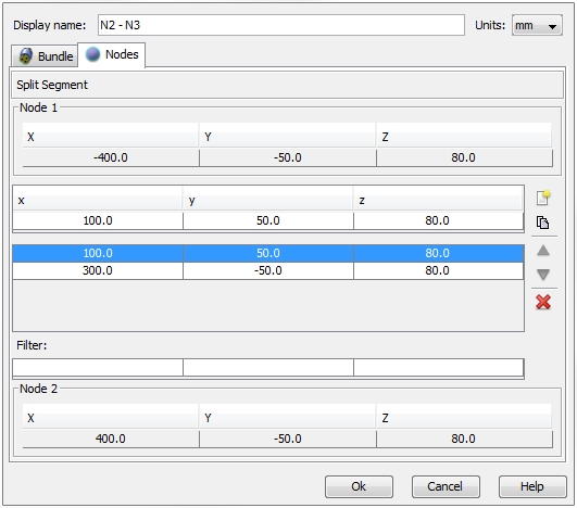
In the figure above we see that two additional nodes were created.
Subdivide a selected segment 
Pressing the button leads to the dialog box as shown in the figure
below:

The length of the original segment is the default value in New Maximum Subsegment Length
field. Entering a value of 200.0
and pressing the Apply button
automatically generates interim nodes on this segment. in such a way that
the segments of the new sub-segments do not exceed the specified limit.
The result can be seen by opening the Nodes-tab
inside the Segment Edit dialog
as explained above (see the figure below):

NOTE:
All cable bundles with a de-activated Fixed
flag will be automatically bundled as soon as the modeling process will
have been started. Be aware this might lead to different simulation models
and therefore to different simulation results. Hence, reproducibility
is only guaranteed if the Fixed
flag is activated.
