Topology Overview
A cable harness in CST CABLE STUDIO consists of the following objects:
Nodes, Segments,
Routes, Cables
and optionally Connectors. Cables
are composed of single wires that are arranged in various ways to twisted cables, ribbon
cables or cable groups.
In addition, cables can be shielded with braided
or solid shields (see Cable
Navigation Tree). Each single wire in a cable or cable bundle carries
its individual electrical Signal.
At either side of single wires or cables there are Terminals
enabling electrical loadings definition. All cable terminals at a certain
node in the 3D space can be gathered in a connector.
Routes comprise Nodes and Segments (and also the objects Traces).
Nodes are defined locations in
the 3D space, Segments are defined
between node pairs, and Traces
refer to a certain sequence of Nodes. So a Route defines a special path
for an amount of cables. The relationship between Nodes, Segments and
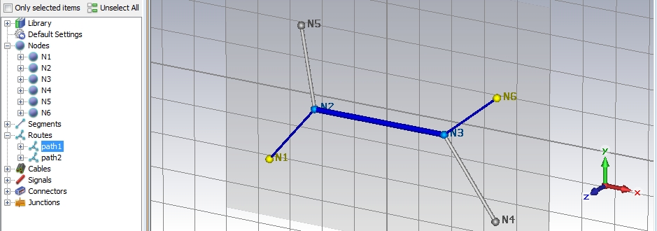
Routes can be best explained by a small example. The figure below presents
a topology consisting of six Nodes that are combined by five Segments. There are two Routes
defined: the first is called path1
and is defined by the N1-N2-N3-N6.
The second is called path2 and
defined by the path N5-N2-N3-N4.
It is obvious that both routes have one common segment N2-N3.
In Route path1 four different
cables are laid. The specific arrangement of the cables in their common
cross-section is called bundle
and is, by default, equal along all segments. The bundle is displayed
in the Cross Section window when
selecting the Route path1 in
the Cable
Navigation Tree as shown in the figure below:

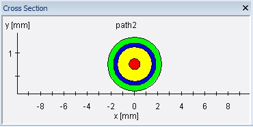
Inside route path2 there is
laid only one single coaxial cable that can also be displayed in the Cross Section window as shown in the
figure below:
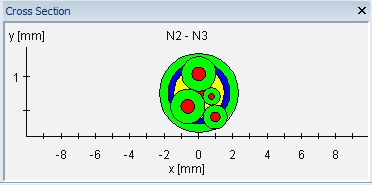
When going into the Cable
Navigation Tree and selecting segment N2-N3
the cables from the two different Routes
path1 and path2 overlap
as can be seen in the figure below. In section Segments
it will be explained how this overlap can be removed.
In CST CABLE STUDIO the user has the possibility to define the cable’s
topology step-by-step by using the specific dialogs for Nodes, Segments,
and Routes. But he ca also start directly in the Routes
dialog box and define all required nodes and segments there. Particularly,
in the Routes dialog box it is possible to define a Route by means of
Traces define a sequence of certain nodes. When doing so, the corresponding
segments are automatically created then.
In the following sections it will be explained how to create Routes
step-by-step by using the individual dialogs for Nodes, Segments, and
Routes. Furthermore, it will be explained how to create Routes by
using the function "Route from
Curve".
Note:
Nodes and
Segments can be part of different
Routes. Each segment contains
its individual cable bundle that can change from one segment to the other.
Routes
can be defined as stubs containing several traces and a number of branches.
In case of a stub, single wires have got more than two ends terminals)
respectively
