
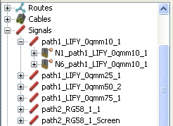
The program automatically generates a unique Signal for each wire inside a cable - a single wire carries one signal, a ribbon cable e.g. has got more than one signal. This means, depending on the kind of cable, a certain number of signal names will be created. A signal name can be changed by selecting the signal in the Cable Navigation Tree and editing it. Each signal normally owns two separate Terminals - in case of a Route with stub traces (see Adding a stub to a Route) the number can be three or more (depending on the number of stubs). The terminals appear as pins in the schematic block later on. All signals will be stored in the Signals folder inside the Cable Navigation Tree as shown in the figure below. In order to display the terminals of a signal, just select the signal and expand it as the figure shows for signal path1_LIFY_0qm10_1:
NOTE:
It is strongly recommend defining meaningful cable names during the bundle preparation inside the Route Definition dialog box. The reason is that cable names are used when composing signal names and cable terminal names. The more significant those signal names and cable terminal names are the easier it is for you to identify them.
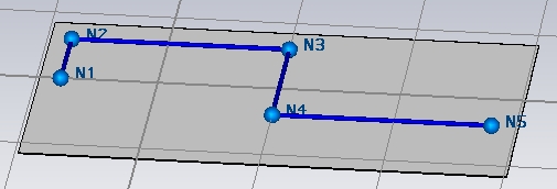
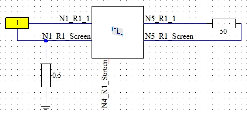
The Route includes a coaxial cable (RG58) and the corresponding schematic is shown in the figure below:
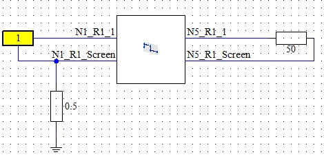
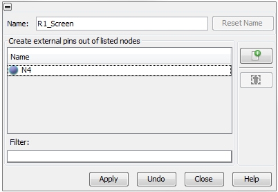
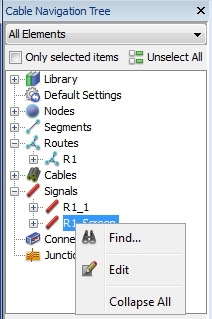
Now the user may be interested on the voltage of the screen at Node N4. In order to set a probe on this point, an additional pin has to be generated. This can be done by selecting Cable Navigation Tree: Signal, right mouse clicking on signal R2_Screen and choosing Edit from the pull-down menu as shown in the figure below:
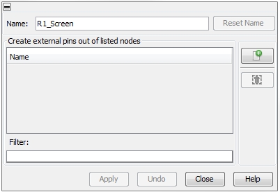
 Add nodes as new terminals. Pressing this button provides
a list of all internal Nodes the Signal is passing by.
 Remove selected Node
