Modeling
Modeling  2D(TL) Modeling
  Modeling
Once the meshing is completed the user
has to decide on the characteristic features the equivalent circuit of
the cable harness should get. This can be done with the help of the Modeling tab.
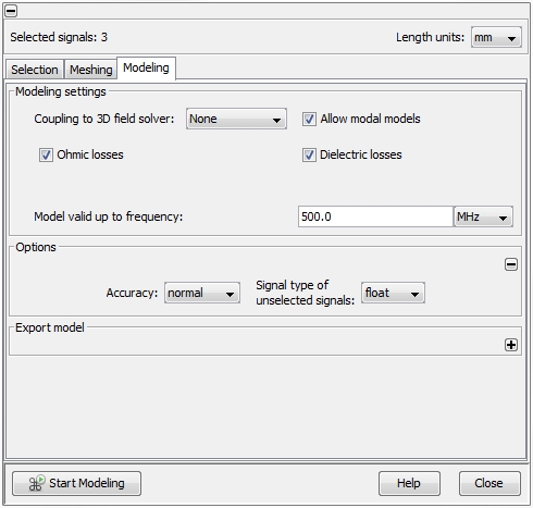
Coupling
to 3D field solver
There are three options how a simulation can be performed and the options
are related to the kind of coupling with a 3D full wave solver:
None: it
is the standard workflow and means there is no coupling to a 3D full wave
solver. The standard workflow is possible in both frequency- and time
domain.
Uni-directional:
there are two options how a cable model can contribute. Either the cable
model acts as a field source (=
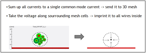
radiation) where all currents
inside a Route are summed up and impressed as a current filament into
the 3D mesh. Or the cable model acts as a field
receiver (= irradiation)
where the electric field along a Route will be taken from the 3D mesh
and impressed as voltage sources to every unshielded wire inside the Route.
The uni-directional workflow is possible in both frequency- and time domain.
Bi-directional:
here, the same current summation and electric field
evaluation is done as in the uni-directional case. But in contrast to
the uni-directional case, the currents and voltages are exchanged simultaneously.
The cable model acts as field source and field receiver at the same time.
If a strong interaction between the cable and its electric environment
is expected, the bi-directional coupling will be more accurate than the
uni-directional one. The uni-directional workflow is
possible in both frequency- and time domain.
In case of an uni- or bi-directional field coupling, the equivalent
circuit has to consist of several segments with
lumped elements (resistors, capacitors, inductors) in series. Deciding
for either uni- or bi-directional field coupling makes the Allow
modal models button vanish.
General scheme of current/voltage exchange:
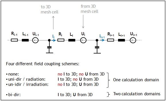
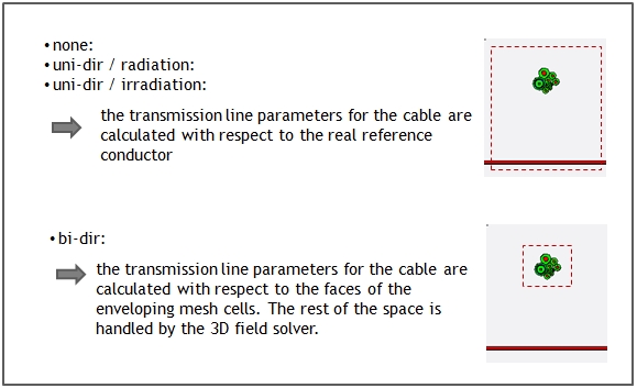
Visualizing the different calculation
domains between none / uni-directional
and bi-directional field coupling:
Assumption for cables with more than
one wire for uni- / bi-directional field coupling:
Allow modal
models
The standard way of modeling transmission lines is to use a series
of segments consisting of so called lumped
elements, which model the primary transmission line parameters
per unit length R', L', C'. The corresponding geometric length of a single
segment is chosen by the program in such a way that its length will be
significantly smaller than the smallest wave length given by the field
Model valid up to frequency. The
shorter the segments are the better the approximation of the transmission
line effect is. The right choice of the segment length has an serious
impact on an important transmission characteristic: the phase velocity
or transmission delay. The internal rule is: a segment must have a maximum
length of 1/20th. of the smallest wave length. The lumped
elements model is the only choice when it has to be used for an
uni- or bi-directional field coupling.
In case of no field coupling, the user can decide to use modal
models instead. Modal
means the cable is not modeled by its primary transmission line parameters
but by its secondary parameters wave
impedance Z and transmission delay
t.
A simple modal model consist of two resistors on each side modeling the
wave impedance Z. In addition, there are two controlled voltage sources
on both sides: the voltage source on one side at time point "t" is controlled by a voltage which
existed at time "t-t"
on the other side of the transmission line.
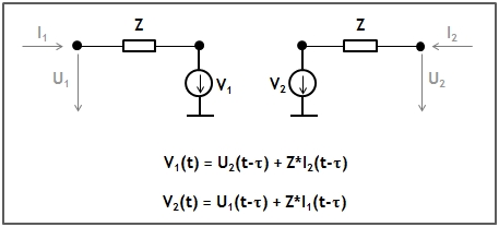
There are two important advantages
of the modal model: First, the
transmission delay is an essential
characteristic of the model and has not to be approximated as it is the
case for the lumped models. Therefore,
the modal model is more accurate
than the lumped model in any case. Second, a modal
model needs only one single segment to describe the whole transmission
line, no matter how long the transmission line actually is. Therefore,
the modal model leads to less complex models in case of electrical long
transmission lines.
The disadvantage of modal models
may be an increased simulation time during a transient analysis, when
even very short cable segments are modeled by modal models, too. This
is because the maximum time step during a transient task must no exceed
the transmission delay of the shortest modal model (otherwise the model's
delay characteristic wouldn't be resolved). If the Allow
modal models button is activated the program looks for cable segments
which equal or exceed the minimum wave length (specified by the field
Model valid up to frequency)
and model them as modal models.
The remaining, electric short segments will be still modeled as lumped models.
Model
valid up to frequency
With the help of this field, the user determines the maximum
valid frequency range of the model. In case of an
unchecked Allow modal models
button this frequency value should be determined sensible, because the
higher the frequency the more complex the resulting equivalent circuit
and this affects the speed during the later network simulation. There
is a upper frequency limit that can not be exceeded. This is because the
modeling of the transmission lines is done by static capacitances and
inductances. This approach demands the dimension of the transmission line's
cross-section to be significantly smaller than the shortest wave length
of the signal traveling on the transmission line. As a result the equivalent
circuit generated after the modeling process has an upper frequency limit
and the usage of this circuit within CST DESIGN STUDIO
is only allowed up to this limit.
Ohmic losses
This button controls the modeling of the frequency dependent ohmic
losses or in other words the Skin effect.
By checking this button the Skin effect will be taken into account. The
program approximates the increase
in ohmic resistance and decrease in internal inductance of a conductor
over the specified frequency range, from DC up to the maximum frequency
specified in the field Model valid up
to frequency. The way of how the impedance changes over frequency
depends on the general shape of the conductor. The program distinguishes
between circular wire shapes and
thin strip shapes. For both shape
types CST CABLE STUDIO provides a solution for the two different kinds
of model interpretations inside the circuit simulation. For a more detailed
explanation see Ohmic
loss modeling.
Dielectric losses
This button allows to take into
account the loss angle of all
isolating materials. As a prerequisite the loss angle has to be assigned
to the corresponding materials in the Material
Library. The program approximates a constant loss angle over the specified
frequency range, from DC up to
the maximum frequency specified in the field Model
valid up to frequency. The crucial point in dielectric loss modeling
is to keep the model causal.
CST CABLE STUDIO provides a solution for the two different kinds of model
interpretations inside the circuit simulation. For a more detailed explanation
see Dielectric
loss modeling.
Options frame
In order to determine the primary transmission line parameters, a static
two-dimensional field calculation has to be performed. This is done using
the Methods of Moments on basis
of a meshed cable cross-section. With help of the
Accuracy field, the user is able
to control the mesh with respect of different degrees of accuracy:
normal
medium
high
very high
Switching from normal to medium increases the number of mesh
elements by a factor of two, thus yielding more accurate models. In this
case the calculation effort will increase with the power of three, though.
In the same way a factor of 2 is applied when changing from medium
to high or from high
to very high. The default value
is normal and this is sufficient
for most of the typical cross-sections.
With the help of the Signal Type of
Unselected Signals field, the user is able to control whether unselected signals are treated as grounded or floating
wires during the static field calculation. Floating or grounded wires
won't be modeled with an equivalent circuit but will affect the capacitance and inductance
of the transmission line system. A floating conductor has no specific
load conditions and therefore doesn’t hold a special electric potential.
A ground conductor on the other
side is shortened to ground and holds earth potential (0V)
everywhere. A switch from float
to ground or vice versa can change
the capacitances and inductances
of the selected signal, but usually has only minor effect on the modeling
results. The default value is float.
Export model frame
Besides the standard workflow of simulating the equivalent circuit
with CST DESIGN STUDIO there is the possibility to export the circuit for the usage within another circuit
simulator. After the modeling has finished the Export model frame allows to export
the generated equivalent circuit in various SPICE formats. In the Export to file field the user can specify
the directory and file name where the equivalent circuit should be stored.
The Model name
field allows the definition of the circuit's name, which will appear in
the header of the resulting model file (e.g. in the .SUBCKT line of the
SPICE equivalent circuit). The Simulator
field gives a selection of syntax formats the model can be written to.
A click on the Export Model button on the bottom right starts the
export process.
Start Modeling
The modeling process can be started by pressing the Start Modeling
button. If the meshing procedure hasn’t been started before (by
pressing the Start Meshing
button in the Meshing tab) it
will be automatically done now. At the end of the modeling process an
equivalent circuit will be created and can be used for a further simulation
in CST DESIGN STUDIO.


 2D(TL) Modeling
  Modeling


