Meshing
Modeling  2D(TL) Modeling
  Meshing
Once the signal selection is completed
the user has to determine in which way the geometry shall be extracted
and prepared for the calculation of the static 2D transmission line parameters.
This can be done with the help of the Meshing tab.
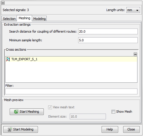
Search Distance for coupling for different
routes
In general, only cables which are located inside a
Segment
can be treated as electromagnetic coupled. A segment is defined as a straight
junction between two Nodes
and may include cables from different Routes
(see Edit
a selected segment). But if different
segments are very close and in parallel to each other the cables inside
have to be coupled. The Search Distance
for coupling of different routes field defines the distance within
different segments will be joined together.
The figure below shows two routes, which are separated in a distance
of 15 mm. Route R1
includes two, route R2 includes
one wire:

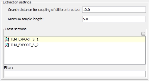
If the Search Distance for coupling
of different routes parameter is chosen to 10
mm, two different segments will be generated after the Start
Meshing button has been pressed. This can be checked by expanding
the Cross sections frame and
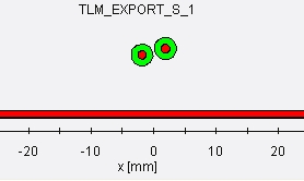
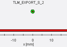
selecting one of the two generated segments. The cables of the corresponding
segment will be displayed in the Cross
Section window. The figures below show that not only the cables
are located inside the segment's cross-section but also the relevant part
of the ground plane.
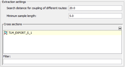
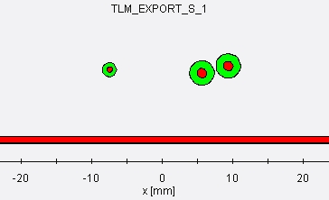
If the Search Distance for coupling
of different routes parameter is chosen to 20
mm, a single segments will be generated including the cables of
both routes in a corresponding distance to each other. This can be checked
by again expanding the Cross sections
frame and selecting the single segment (see figures below):
Note:
The search distance has only effect on neighboring
signals in other routes. All cables lying in the same route as the selected
signals are automatically taken into account regardless their distance.
Minimum sample length
This parameter limits the minimum length a segment can be generated.
The parameter is useful if a complex harness has been imported via the
Nastran interface (see Cable
Data Import) and the number of overall segments shall be limited.
Mesh preview frame
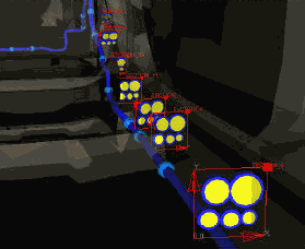
By pressing the Show Mesh button all generated segments along
the cable harness will be shown in the Main
View by small cable symbols. These
symbols indicate where and how the cable harness was subdivided for the
later 2D transmission line modeling. The Element
size field enables to specify
the size of the symbols. The usage of these mesh view option is
more obvious when dealing with complex cable harness as shown in the figures
below.
.


 2D(TL) Modeling
  Meshing


