Selection
Modeling  2D(TL) Modeling
  Selection
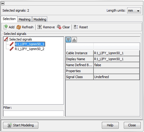
The figure below shows the Selection
tab. On the left side there is the Selected
signals frame. By default, all available cables from the Cable
Navigation Tree will be listed inside this frame. Every signal causes
a representation in the equivalent circuit to be generated (see Signals
and Terminals). Therefore, the user has to decide on cables which
should not take part in the signal transmission. In general, all existing
cables will be taken into account during the calculation of the corresponding
transmission line parameters. But there is a difference on how the cables
will be treated, depending on whether the cables are selected or not.
A selected cable will appear in the generated equivalent
circuit explicitly - with corresponding pins for the cable's terminals
(see Signals
and Terminals ). Not selected cables will be considered either as
grounded or floating
during the calculation of the transmission line parameters (see Modeling).
They won't appear explicitly in the generated equivalent circuit but,
of course, will affect the transmission line parameter of the existing
signal cables.
The icons on the top of the Selection tab enable actions which are
explained below. The meaning of each icon is also explained by tool-tips.
To see a tool-tip just move the mouse-pointer over the corresponding icon:
 Add: adds
those signals which are selected inside the Cable
Navigation Tree
 Refresh: adds
the signals which are selected in the Cable
Navigation Tree into the list, but removes all others (which are not
selected in the Cable Navigation Tree).
This function is very useful when the complete set of signals in
the list should be changed.
 Remove: removes
the selected signals from the list. Removing a signal from the list does
not mean removing the wire from the cable harness. It only means that
the wire will be considered either as floating
or grounded during the calculation
of the transmission line parameters. The decision
on an either floating or grounded can be done inside the Options
frame in the Modeling tab (see
Modeling).
 Clear:
removes all signals from the list
 Reset:
highlights the location of all listed signals in the Main View


 2D(TL) Modeling
  Selection
 Add: adds
those signals which are selected inside the Cable
Navigation Tree
 Refresh: adds
the signals which are selected in the Cable
Navigation Tree into the list, but removes all others (which are not
selected in the Cable Navigation Tree).
This function is very useful when the complete set of signals in
the list should be changed.
 Remove: removes
the selected signals from the list. Removing a signal from the list does
not mean removing the wire from the cable harness. It only means that
the wire will be considered either as floating
or grounded during the calculation
of the transmission line parameters. The decision
on an either floating or grounded can be done inside the Options
frame in the Modeling tab (see
Modeling).
 Clear:
removes all signals from the list
 Reset:
highlights the location of all listed signals in the Main View