Harness View Attributes
Edit Cabling  Properties
  Harness View Attributes
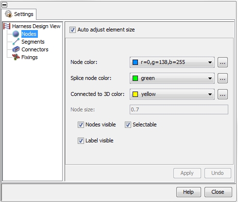
The Harness View Attributes
dialog box enables the user to control the appearance of the following
objects inside the Main View:
Nodes
Segments
Connectors
Fixing

Nodes
By selecting Nodes on the
left side of the dialog box all parameters to control the appearance of
the Nodes will be provided:
Node Color:
allows the color definition of all nodes beside splice
nodes (Defining
a new Route).
Splice Node Color:
defines the color of splice nodes
(Adding
a stub to a Route).
Grounded Node Color:
defines the color of the grounded nodes (Editing
an existing Route).
Node Size:
defines the visualization size of all nodes.
Nodes Visible:
defines whether the nodes shall be visualized or not
Selectable:
defines if the nodes shall be selectable in the Main
View
Label Visible:
defines whether the node labels shall be visualized or not
If the Auto
adjust element size check button is activated the parameter Node Size will be set to its default:
After de-activating this parameter can be set manually.
Segments
By selecting Segments on the
left side of the dialog box all parameters to control the appearance of
the Segments will be provided:
Segment Color:
allows the color definition of the segments (Edit
a selected segment)
Loaded segment color:
allows the color definition of the loaded segments (Editing
an existing Route)
Segment Maximum Size:
the visualized diameter of the segments is related to the number of cables
inside the segment. With the help of this value one defines the upper
limit for all segments.
Segment Minimum Size:
the visualized diameter of the segments is related to the number of cables
inside the segment. With the help of this value one defines the lower
limit for all segments.
Segments Visible:
defines whether the segments shall be visualized or not
Selectable:
defines if the segments shall be selectable in the Main
View
Label Visible:
defines whether the segment labels shall be visualized or not
If the Auto
adjust element size check button is activated the parameters Segment Maximum Size
and Segment Minimum Size will
be set to its default: After de-activating these parameters can be set
manually.
Connectors
By selecting Connectors on
the left side of the dialog box all parameters to control the appearance
of the Connectors will be provided:
Connector Color:
allows the color definition of the connectors
Connector Maximum
Size: the visualized size of the connectors is related to the number
of pins on the connector.
Connector Minimum
Size: the visualized size of the connectors is related to the number
of pins on the connector.
Ratio Width : Height
: Length: all connectors are shown as a box. The field defines
the ratio of width, height
and length of the
boxes
Connectors Visible:
defines whether the connectors shall be visualized or not
Selectable:
defines if the connectors shall be selectable in the Main
View
Label Visible:
defines whether the connector labels shall be visualized or not
If the Auto
adjust element size check button is activated the parameters Connector Maximum Size
and Connector Minimum Size will
be set to its default: After de-activating these parameters can be set
manually.
Fixings
A Fixing is a special object
that can not be defined manually. These objects does not have any electrical
meaning but define the spots where a cable harness is fixed to the chassis.
They might be imported during the harness import if defined inside the
STEP AP2.12- kbl-file by a special
CAE system (Cable
Data Import).
By selecting Fixings on the
left side of the dialog box all parameters to control the appearance of
the Fixings will be provided:
Fixing Color:
allows the color definition of the fixings
Fixing Size:
defines the size for all fixings.
Fixing Visible:
defines whether the fixings shall be visualized or not
Selectable:
defines if the fixings shall be selectable in the Main
View
Label Visible:
defines whether the fixing labels shall be visualized or not
If the Auto
adjust element size check button is activated the parameter Fixing Size will be set to its default:
After de-activating this parameter can be set manually.


 Properties
  Harness View Attributes