|
微波射频仿真设计 |
|
|
微波射频仿真设计 |
|
| 首页 >> Ansoft Designer >> Ansoft Designer在线帮助文档 |
|
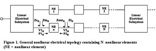
System Simulator > Single-Tone Frequency Domain AnalysisSingle tone frequency-domain analysis is applicable only to electrical systems comprised of linear/nonlinear frequency-based elements. Systems containing functional time-based elements may not be analyzed in the frequency domain. Single-tone frequency analysis ignores any intermodulation products/harmonics generated by nonlinear elements in the system, such as amplifiers, mixers, and frequency multipliers. Frequency domain analysis is applicable to a general multi-channel nonlinear electrical topology like the one shown in the following figure:
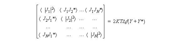
Such a topology is typically comprised of multi-port linear passive elements and two-port linear/nonlinear active elements. In addition, it is assumed that the system has only one input port where a single-tone RF source is applied during analysis, such as those sources with swept parameters. Single-tone frequency domain analysis is primarily based on evaluating the admittance matrix Y and the corresponding noise based correlation matrix J. The admittance matrix may then be used to solve for the system’s internal/external voltages using Kirchoff’s Current Law (KCL) linear formulation. The Y-parameter representation for two-port/multi-port elements may be easily obtained from the S-parameter characterization by means of commonly used transformation formulas [1]. For an RF source with a given input carrier frequency fc and an available input power P1 applied to the input port of the system, the Y-parameters and noise correlation matrices are calculated for each passive and active electrical element within the entire system. These matrix calculations are typically associated with each element’s single-tone input frequency. In general, during single-tone frequency domain analysis, the frequency within the system may be translated due to the presence of mixers. It is assumed that this frequency translation (i.e., mixing) is linear in nature (i.e., does not generate any additional harmonics) to ensure the presence of a single-tone at each node within the system. Analysis of harmonics and intermodulation products generated by mixers and nonlinear amplifiers will be discussed later in the section on Multi-tone Frequency Domain Analysis. For an N-port linear electrical element, the NxN Y-parameters matrix relates the element’s voltages and currents using the following set of linear equations:
Using this NxN Y-parameter matrix, the passive noise correlation matrix may be derived as follows [2]:
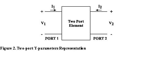
where:  = Statistical average For a two-port active or passive element (Figure 2), the 2x2 Y-parameter matrix relates the element’s voltages and currents using the following set of linear equations:
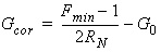
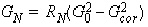
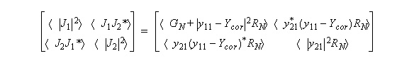
For an active linear or nonlinear electrical element, the Y-based active noise correlation matrix is given by [2]:
Where: 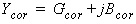

Based on the connections of the different elements within
the system, the overall system Y 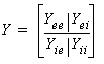 is the System’s
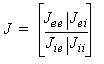 is the System’s
Where i
= Number of internal ports in the system The system’s 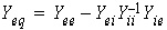
and 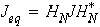
with 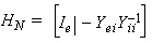
and
The topics for this section include: Algorithm for Single-Tone Y-parameters Evaluation of Nonlinear Systems Topology Restrictions for the Sweep Domain Assumptions Made for Sweep Domain Measurements Topology Restrictions for the Budget Domain Assumptions Made for Budget Domain Measurements
HFSS视频教程 ADS视频教程 CST视频教程 Ansoft Designer 中文教程 |
|
Copyright © 2006 - 2013 微波EDA网, All Rights Reserved 业务联系:mweda@163.com |
|

 = Noise bandwidth (specified in the frequency
domain solution setup dialog)
= Noise bandwidth (specified in the frequency
domain solution setup dialog)
 Y-parameters matrix.
 passive and active noise correlation matrix
.
passive and active noise correlation matrix
. = Total number of ports in the system
 Y-parameters
and noise correlation matrices
Y-parameters
and noise correlation matrices  Y-parameters and noise correlation
matrices
Y-parameters and noise correlation
matrices  identity matrix


