|
微波射频仿真设计 |
|
|
微波射频仿真设计 |
|
| 首页 >> Ansoft Designer >> Ansoft Designer在线帮助文档 |
|
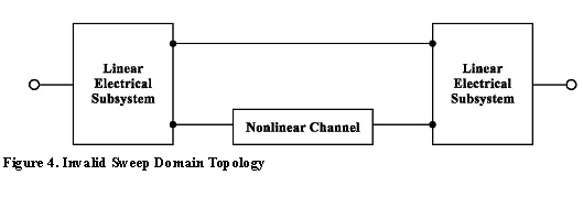
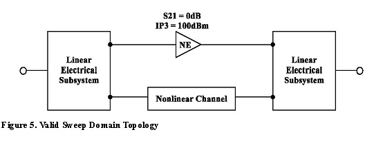
System Simulator > Topology Restrictions for the Sweep Domain1. A valid topology consists of arbitrary linear electrical topologies interconnected by an arbitrary number of cascaded nonlinear electrical channels (containing nonlinear 2-port data, amplifier, mixer and/or frequency multiplier). An example of an invalid topology is shown in Figure 4. This topology would become valid with the added nonlinearity in Figure 5.
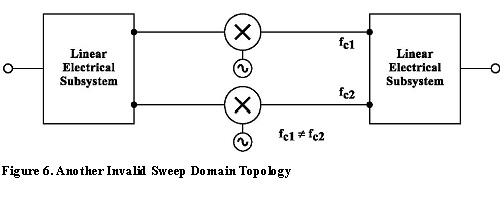
2. Only electrical components are allowed for the frequency-based sweep domain. In addition, linear/nonlinear electrical subsystems are allowed. 3. For each input frequency tone, each node inside the system must have only a single frequency tone present (e.g., multiple mixer paths may not lead to different frequencies at a given node in the system. This condition should yield an analysis error message). Figure 6 below represents an invalid topology for sweep domain analysis.
4. All external ports must have an interface port connection. 5. All nonlinear elements, except mixers, are assumed
to have one output frequency for each input frequency. In other words,
Intermodulation Distortion (IMD) harmonics are ignored in this analysis.
Nonlinearities can be defined based on the compression effects (e.g.,
Pout vs. Pin or S 6. Mixers will generate a single output frequency for each input frequency, unless a mixer spur table has been provided. Mixer spur tables can be provided through a data file or circuit co-simulation.
HFSS视频教程 ADS视频教程 CST视频教程 Ansoft Designer 中文教程 |
|
Copyright © 2006 - 2013 微波EDA网, All Rights Reserved 业务联系:mweda@163.com |
|