|
微波射频仿真设计 |
|
|
微波射频仿真设计 |
|
| 首页 >> Ansoft Designer >> Ansoft Designer在线帮助文档 |
|
Dynamic Links and Solver On Demand > Setting Up Models for a Component TypeThe first step is setting up for Solver On Demand is to define the models that will be available for each component type. 1. Open the Definitions folder on the project tree, and then open the Components subfolder. 2. Double-click the component in the list to open the Edit Component dialog. This dialog sets parameters that affect all components of the given type. 3. Select the Solver On Demand tab:
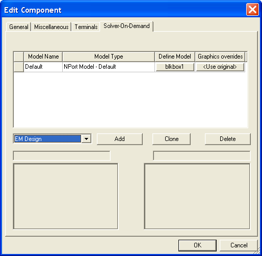
To add a model for Solver On Demand: 1. Click on the pulldown next to the Add button to display a list of the available model types. Select the type of model from the pulldown. Click Add. A new model of the selected type is added to the list. The symbol and footprint preview windows at the bottom of the dialog are automatically updated to reflect whatever changes you make to a component’s symbol/footprint definitions. 2. Click in the Model Name field for the new model and type the name you want to use for this model (or accept the default which already appears in the Model Name field). Note that when you highlight a Model Name, its symbol and footprint (if defined) are automatically previewed in the windows at the bottom of the dialog. These preview windows are automatically updated to reflect whatever changes you make to the component’s symbol/footprint definitions. 3. Click the button in the Define Model column to open a Cosim or Netlist definition dialog that is specific to the model type. 4. Click the button in the Graphics overrides column to open an Edit overrides dialog to modify Symbol/Footprint settings or Terminals settings. For more information see General Tab, Terminals Tab, and Solver On Demand Symbol and Footprint Override. 5. Repeat steps 1 through 4 to create all the models you wish to use for this type of component. 6. Click OK when you have defined all the models for this component type. Repeat the above procedure to specify models for all components that will be simulated using Solver On Demand.
Component Type Definitions Solver On Demand allows you to define any number of the following: • Planar EM cosimulation models through a Planar EM design. The footprint geometry is copied over to a new Layout. You can decide at definition time whether the design will be shared for all instances or if a new design should be created. • HFSS cosimulation models through a Dynamic Link component. You can decide at definition time whether this dynamic link component will be reused across instances or if a new one should be created for each instance. • Netlist models defined directly with a netlist editor. • Various models selected from component libraries, including: Planar EM, Custom, Netlist, MultiProduct Netlist, C Model, NPort Model, HFSS Model, Q3D Model, SIwave Model, Parametric NPort Model.
Select from the following to define a particular component model type: • Custom • Netlist • Bypass • C Model
HFSS视频教程 ADS视频教程 CST视频教程 Ansoft Designer 中文教程 |
|
Copyright © 2006 - 2013 微波EDA网, All Rights Reserved 业务联系:mweda@163.com |
|


