Basic Component Dialogs
This page gives a basic introduction on the electrical modeling of
Components. Detailed information
on how to model the different types of components (passive, active, power
supplies) are given in further pages. Why is the assignment of an electrical
model to a component useful? The main advantage of assigning an electrical
model to a component is because CST PCB STUDIO already knows about all
the electrical connectivity between the component pins and the assigned
nets. Therefore, the user only needs to assign the appropriate electrical
models to the corresponding pins to complete all information necessary
for a whole simulation set up. The assignment of electrical model is a
prerequisite for the convenient workflows (see Solver
Overview).
Edit Components ComponentEdit
Components
ComponentEdit
Components
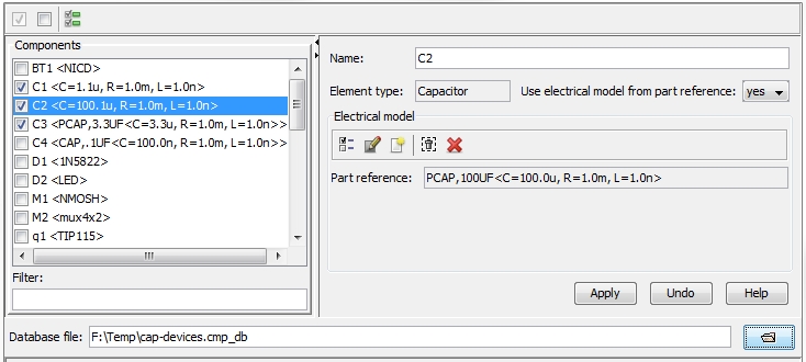
The Edit Components dialog
box is divided into two columns. On the left side all existing components
(stored and visualized in the Navigation
Tree: Components) are listed. Selecting
a certain component displays its corresponding definition at the right
column side.
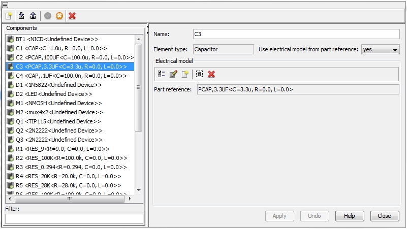
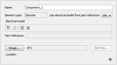
Name: A
component must have an unique name.
Element type: The
Element
type of a component will be
imported by the EDA import and has no
meaning for the electrical model assignment. The information can be used
to assign the appropriate electrical model to he component. There are
four different Element
types:
Resistor
Capacitor
Inductor
Discrete
Use electrical model from part reference:
If the
component is passive CST PCB
STUDIO offers two possibilities of how to assign an electrical model.
The assignment can be done either by referring to an existing model in
the Parts Library (see Parts
Library) or by assigning a local
model. The advantage of referring to a model in the Parts Library is that
any change on the model affects all components which refer to the corresponding
part. Typically, verified and proven models shall be stored in the Parts
Library. In contrast, the local assignment of model may be helpful if
the effect of a single component should be analyzed.
Referring
to Parts Library: (see Parts Library)
The tool bar inside the Electrical
model frame (see figure below) enables the following actions:
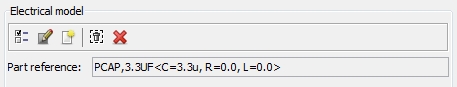
 Select part:
A certain part from the available part list can be selected. Currently
the component refers to part PCAP,3.3uF.
Select part:
A certain part from the available part list can be selected. Currently
the component refers to part PCAP,3.3uF.
 Edit part: Opens the Edit
Part dialog box of the currently referred part (see Edit
Part).
Edit part: Opens the Edit
Part dialog box of the currently referred part (see Edit
Part).
 New part: Opens
the Create New Part dialog box
of the currently referred part (see Create
New Part).
New part: Opens
the Create New Part dialog box
of the currently referred part (see Create
New Part).
 Remove part:
Removes the current reference to the part. This action does not
delete the corresponding part in the Parts
Library.
Remove part:
Removes the current reference to the part. This action does not
delete the corresponding part in the Parts
Library.
 Delete part:
Deletes the current reference to the part. This action does not
delete the corresponding part in the Parts
Library.
Delete part:
Deletes the current reference to the part. This action does not
delete the corresponding part in the Parts
Library.
Local
Model Definition:
If the user decides for a local
model definition the right
side of the dialog box changes as shown in the figure below.
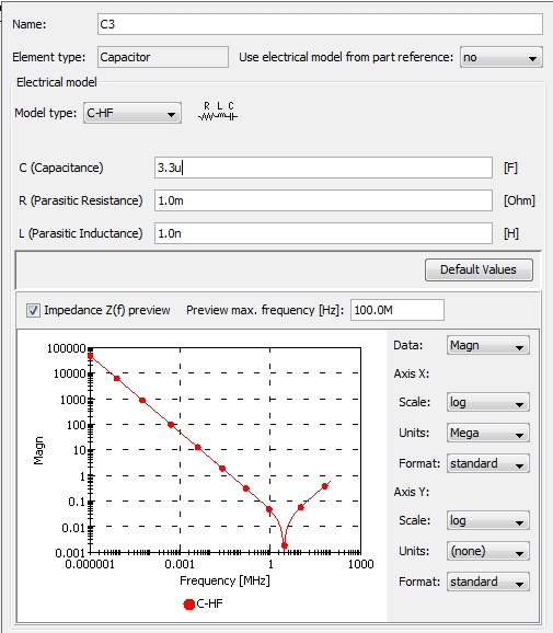
Five general Model
types are available:
The tool bar at the top of the dialog box (see figure below) offers
the following features:
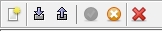
Create new component
Opens a dialog box to create a new component
(see figure below). The usage of the dialog is identical to the description
above.
Load
part database from disk 
There is no real Import function
for components since the number and location of components on the PCB
is fixed. Instead, there is the Load
part database feature which provides two
functions: first, it imports new part models and adds them to the Parts Library,
identical to the Import part function (see Import
Parts). But in a second step, the function scans the imported file
for component names (the so called reference
designators). If a reference
designator of an imported part matches the reference designator of an
existing component, the existing part model (or the existing local model
(see Edit Component) will be replaced by
the new imported one.
There are four different kind of data formats which can be imported:
CST Component Database (*.cmp_db): the
internal format which enables the user to import of all types of device
models that can be exported as well (see Export
Components)
2-pin RLC from csv file (*.csv): Excel
file, every row includes R- L, C- data for a corresponding series circuit
topology (see Import Parts)
2-pin RLC from Cadence report file:
specific ASCII file, every row includes comma separated
R- L, C- data for a corresponding series circuit topology (see Import
Parts)
2-pin CR5000 Parts List: specific ASCII
file, every row includes comma separated R- L, C- data for a corresponding
series circuit topology (see Import
Parts)
The function will be explained with an example: An Excel
file including 2-pin
RLC csv data shall be imported,
see figure below. Column A includes a reference
designator (= component name) for
each part model:
The figure below shows an extract from a component list. At the end
of the list there is the component R1900
which has no model data:
The Excel file from above includes the reference designator R1900
and therefore, the Load Part Data function will assign
the corresponding part model to the R1900
component. After performing the Load
Part Data function a message on the number of updated components
will be given. The result can be seen in the figure below:
Export
components 
Pressing the export button shows the dialog box shown in the figure
below. On the left side the list of all available components is displayed.
All components (or more precise: the electrical model from all components)
which should be exported have to be tagged:
On the right side, the definition of the currently selected component
is shown (and can still be edited). The ASCII file where the electrical
models of the components should be exported has to be specified inside
the Database file field. The models
will be exported in a specific internal file format, CST
Components Database (*.cmp_db).
All available Model types
C-HF
R-HF
L-HF
I/O Device
Power Supply
Disable selected
component 
For some analysis tasks it is useful to remove an existing component
from the PCB. Pressing the Disable
button removes the selected component and its related pins and pad stacks
from the board.
Enable selected
component 
Pressing the Enable button
brings the disabled component and its related pins and pad stacks back
to the board.
Delete selected
component
Pressing the Delete button
really deletes the component, in contrast to the Disable
button (see above).