|
微波射频仿真设计 |
|
|
微波射频仿真设计 |
|
| 首页 >> Ansoft Designer >> Ansoft Designer在线帮助文档 |
|
HFSS and Planar EM Simulators > Creating an Edge Port1. Select the signal layer on which the port lies. 2. On the Edit menu, click Select Edges. 3. Click the edges of the model on which the port lies. 4. On the Draw menu, click Port > Create. The edge port is listed under Excitations in the project tree.
To edit the port’s properties, double-click the edge port in the project tree. The Edge Port Definition dialog box appears: 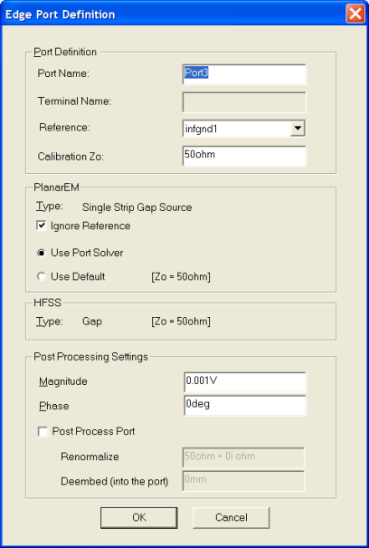 You can perform the following functions: • Change the port’s name. • Vary the current excitation. • Renormalize the port to a specific port impedance. • De-embed the port.
A port can be split across multiple signal layers. It can be made of up to three different line segments on three different primitive objects. Ports located over apertures in ground planes can generate incorrect results. Designer will automatically display a warning message if referencing a gap source to the nearest ground would produce such an error.
HFSS视频教程 ADS视频教程 CST视频教程 Ansoft Designer 中文教程 |
|
Copyright © 2006 - 2013 微波EDA网, All Rights Reserved 业务联系:mweda@163.com |
|


