|
微波射频仿真设计 |
|
|
微波射频仿真设计 |
|
| 首页 >> Ansoft Designer >> Ansoft Designer在线帮助文档 |
|
HFSS and Planar EM Simulators > Varying the Port ExcitationYou can vary the voltage applied to a model by scaling its magnitude and modifying its phase in the Edge Port Definition dialog box. A schematic of an excitation is shown below. The voltage source model is in series with an impedance that is equal to the characteristic impedance of the port. Hence, renormalizing the port impedance will change the port excitation model. 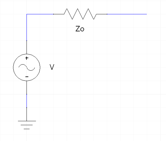
To vary the applied voltage at a port: 1. Double-click the edge port in the project tree. The Edge Port Definition dialog box appears. 2. In the Magnitude text box, enter the magnitude of the voltage applied at the port. In general, you may use the default value of 1 volt. This specifies that the solution's current is scaled so that the excitation source is 1 volt. To view the solution at a different excitation level, enter a different positive value for Magnitude. Only modes with non-zero magnitudes are used in post processing. 3. In the Phase text box, enter a phase of the voltage applied at the port. 4. Click OK.
HFSS视频教程 ADS视频教程 CST视频教程 Ansoft Designer 中文教程 |
|
Copyright © 2006 - 2013 微波EDA网, All Rights Reserved 业务联系:mweda@163.com |
|


