|
|
|
| 首页 >> CST教程 >> CST2013在线帮助系统 |
Mesh View (Hexahedral)
|
|
|
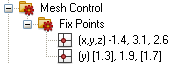
In this folder, all user-defined fixpoints (see below) are listed. The location is printed and the direction(s) in which they will affect the mesh. The active directions are those in ”round” brackets. The values in ”square” brackets are irrelevant for the mesh generation. |
Expanded critical cells/areas
After the structure has been meshed, some mesh cells/areas might have been filled with PEC. In this case, a warning message on top of the Main plot window will appear (for more information see Mesh Generation Overview ).
Fixpoints and density points
Fixpoints: The automatic mesh generator will detect the important points inside the structure and locate fixpoints at these positions. If possible, a mesh node will be located there. When the mesh view is activated, fixpoints are depicted by red dots.
Density control points: These control points are used by the automatic mesh generator to refine the mesh in a particular region if necessary. This is the case, for instance, when the Refine at PEC Edges option is active. When the mesh view is activated, the density control points will be depicted as yellow dots.
User defined fixpoints: The mesh creation may be performed with even more flexibility by creating user defined fixpoints (blue dots). These user defined fixpoints may be created at characteristic points of the model. They are associated to the structure and enable advanced mesh control with fully parametric modeling. To set a user defined fixpoint, select the desired shape and use one of the following tools:
|
|
|
|
|
Modeling:
Picks |
|
|
Modeling:
Picks |
|
|
Modeling:
Picks |
|
|
Modeling:
Picks |
You may specify the direction(s) in which these
fixpoints will be effective. This may be carried out either through the
context menu
of the fixpoints or by selecting Mesh:
Mesh Control![]() Fixpoint List
Fixpoint List![]() Use <x,y,z> Coordinate (
Use <x,y,z> Coordinate (![]()
![]()
![]() ).
).
Controlling the mesh by changing its parameters
The behavior of the automatic mesh generation may
be changed by adjusting its parameters. These parameters may be accessed
from the mesh properties
dialog box (Mesh:
Mesh Control![]() Global Properties,
Global Properties, ![]() ) and the corresponding specials
sub dialog box in the Mesh
Dialog.
) and the corresponding specials
sub dialog box in the Mesh
Dialog.
Controlling the mesh for specific structure elements
It is possible to set several structure element specific mesh control values. They may be reached by selecting the corresponding object and choosing Local Mesh Properties from the context menu.
If specific mesh properties are set for a shape
this is visualized in the mesh view with the ![]() icon.
icon.
Consider for Automesh: Some structure elements may produce many mesh control points and, with this, a very dense mesh, although this structure element may not be important for the simulation. In these cases, the generation of control points for this element may be switched off.
Priorities: The priority number defines an ”importance” of the different solids for the mesh generation. If one solid has a higher priority than the other one, its mesh requirements will be fulfilled in advance of the less important one.
Maximum Mesh Step Width: For structure elements of high importance for the simulation, a maximum step width for every coordinate direction may be specified.
Manual mesh generation
Besides the automatic mesh generation, a manual mesh mode is also available. The automatic mesh generation is switched off as soon as a manual mesh operation is performed.
You may manually add fixpoints by simply clicking
at an edge endpoint (Modeling:
Picks![]() Picks
Picks ![]() ) or a circular edge (Modeling:
Picks
) or a circular edge (Modeling:
Picks![]() Pick Point
Pick Point![]() Pick
Circle Center
Pick
Circle Center
![]() ), depending on the activated mode. After clicking
a proper item, a new fixpoint will be set to the specified location or
an existing fixpoint at this location will be selected.
), depending on the activated mode. After clicking
a proper item, a new fixpoint will be set to the specified location or
an existing fixpoint at this location will be selected.
After selecting a fixpoint, it may be deleted by choosing Delete Fixpoint(s) from the context menu or by pressing the DELETE key.
You may also add,
delete and move
fixpoints from within the fixpoint
list dialog box (Mesh: Mesh Control![]() Fixpoint List,
Fixpoint List, ![]() ).
).
After two fixpoints have been selected (selecting the first one and the holding the CTRL key pressed while selecting the second one) you may also add intermediate fixpoints by choosing the Intermediate option in the fixpoint list dialog box.
See also
Cutting Plane, Mesh Properties, Special Mesh Properties, Fixpoint (Line Endpoint), Fixpoint (Circle Center), Fixpoint (Circle Point), Fixpoint (Edge Center), Fixpoint (Face Center).


HFSS视频教程 ADS视频教程 CST视频教程 Ansoft Designer 中文教程
|
Copyright © 2006 - 2013 微波EDA网, All Rights Reserved 业务联系:mweda@163.com |
|