View Options - General
 Options
  View Options - General View Options - General
Change general view options using this dialog.
Draw frame
Working plane
(ALT+W): Shows or hides the .
Bounding box:
Shows or hides the bounding box of the whole structure.
Background
material: Shows or hides the background material. This option is
available after a solver was started.
Layer stacking:
Shows or hides the multiple layers. Activated by default.
Coordinate system frame
There are two coordinate systems available (see
Coordinate Systems
for more information).
Coordinate
axes (CTRL+A): If activated the axes of the global coordinate system
are visible.
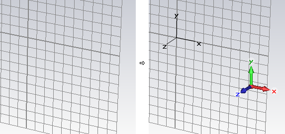
Multicolored
axes: Shows or hides the axes of the global coordinate system.
They are at a fixed position at the lower right corner of the screen.
Axes at origin:
Shows or hides the axes of the global coordinate system at the origin.
Multicolored
WCS axes: The display style of the WCS uvw axes can be changed
between colored RGB (flag activated) and simple black lines.
Show solid coord.
systems:
None:
Show no local solid
coordinate systems.
Selected:
Show local solid
coordinate systems of selected solids (if available).
All:
Show local solid
coordinate systems of all solids (if available).
Information text frame
Draw text :Shows
or hides the info text in the modeler view and the post processing views.
Style:
Changes the appearance of the text.
Field plots frame
Expanded cells
in field plots: Visualizes hexahedral mesh cells that have been
expanded by the mesher because they could not be handled as standard PBA庐
or TST™ cells.
2D Fields on
hidden objects: Shows or hides 2D fields on hidden objects.
Shape representation frame
Wireframe (CTRL+W):
This flag indicates whether all shapes are visualized as simple wire models
or as solid shaded objects.
Shape outline (ALT+O) frame
This option is used to emphasize the edges of the
shapes. This can also be done by pressing the ALT+O
key.
None: No
outline is displayed.
Same as shape:
The outline has a highlighted shape color.
Black: The
outline is black.
Mesh frame (hexahedral meshes only)
Fixpoints:
Shows or hides the fixpoints, density points and other hexahedral mesh
control elements in the hexahedral Mesh
View. (red dots)
Density points: Shows or hides the density points in the
hexahedral Mesh View.
(yellow dots)
Corner correction
lines: Shows or hides the corner correction
lines in the hexahedral Mesh
View. (green lines)
Mark mesh line
crossing: Marks each mesh line crossing in the hexahedral Mesh
View by an additional cross.
OK
Takes the current settings, refreshes the plot
window and closes the dialog box.
Cancel
Closes this dialog box without performing any
further action.
Preview
Takes the current settings and refreshes the
plot window. Use this button to try out different settings. The old settings
will be restored if you leave the dialog box by using the Cancel
button.
Help
Shows this help text.
See also
View Options: Colors,
Specials, Shape
Accuracy, Line
Width, Illumination.


HFSS视频教程
ADS视频教程
CST视频教程
Ansoft Designer 中文教程
|
