

CST DESIGN STUDIO™ offers the possibility of dealing with hierarchical models. This feature is realized by the implementation of this type of block that just represents a placeholder for the sub-model inside the schematic view of its ’parent’ model.
Initially, a CST DESIGN STUDIO block shows no physical behaviour; therefore, it has no internal ports and consequently, it cannot be connected. Within the Block Properties - General dialog box you can open the sub-model's schematic view by pressing the Edit... button. Alternatively, you can perform a double-click over the block to open this view, which is initially empty.
To activate the parent model, select the root 'Drawing' icon in the navigation tree or activate the 'Schematic' tab in the main view.
The sub-model represents a complete model, which you can associate with a geometry unit and a frequency unit that may differ from the units defined for its 'parent' model. Furthermore, you can define tasks, parameters, etc. Some of those definitions affect the parent model's settings as well as some actions, e.g., the insertion of an external port. Be aware of the following interactions:
A limitation of the frequency range for the sub-model is considered for the determination of the limiting frequency bounds of its parent model. If you insert a frequency-bounded block into the sub-model's schematic view, the frequency bounds of the parent model may also change. You should also check the validity of the tasks that define a frequency sweep for the parent model.
Inserting an external port into the sub-model's schematic view means adding an internal port to the corresponding CST DESIGN STUDIO block inside its parent model, as well as removing an external port from the sub-model; this leads to the deletion of the corresponding internal port of the block. This interaction is quite clear, as the internal ports represent the interfaces of the block, which are the ports of the sub-model.
Defining a parameter inside the sub-model leads to the addition of an editable property to the block. The value of the parameter or the property, respectively, can be changed in two ways: You may either edit the block's property inside the Block Properties - Parameters dialog box or modify the parameter's value using the List of Parameters dialog box of the sub-model.
Because the sub-model represents a complete model, you can perform any setting that you can also perform for a parent model. Consequently, except for the interactions that are listed above, the settings for the parent model and a sub-model are independent of each other. Be aware, however, of the following aspects:
A reference block that is contained in the parent model cannot be referenced by a block of the sub-model. Furthermore, a reference block contained in the sub-model cannot be referenced by a block of the parent model.
A parameter defined for the parent model can never be used in a sub-model. Conversely, it is not possible to use a parameter defined for the sub-model inside the parent model, either.
It is also possible to deal with an existing design as a sub-model inside your current design. Therefore, open the Block Properties - General dialog box of the CST DESIGN STUDIO block that shall contain this model and press the Browse... button. Note, if its current sub-model is not empty and you replace it by another one, all components associated with the current sub-model will be removed and all settings will be replaced.
Let us now become familiar with its use step by step. First, create a new project and insert a CST DESIGN STUDIO block into the schematic view by drag’n’drop from the ’Miscellaneous’ section of the block selection tree. Because the block shows no physical behavior it has no internal ports and cannot be connected. There are two possibilities of adding a physical behavior:
Creating a sub-model
Loading a model as a sub-model
Regarding
the first possibility: If you perform a double-click on the block, the
sub-models’ schematic view, which is initially empty, is opened.
Please note that the CST DESIGN STUDIO block is the only block whose property
dialog box is not opened by a double-click, but only by either choosing
Edit![]() Properties from
the menu bar or using the context menu of the block.
Properties from
the menu bar or using the context menu of the block.
We now have an empty sub-model. There are several ways to switch to the ’parent’ model:
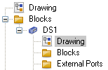
It can be accessed via the navigation tree. You can find the sub-model attached to the block that refers to it.
The sub-model represents a complete model that you can associate with global units that may differ from those of its ’parent’. It may have its own local parameters. Some of the sub-models' settings may affect the settings of the ’parent’ model, while others do not. We will now describe the interaction between model and sub-model in detail.
Assume that there are frequency-bounded blocks inside the sub-model, e.g. some simulated or measured blocks. If you open any special task dialog box, the valid frequency range for the sub-model will be displayed inside the ’Frequency Range’ frame at the top of the dialog box.
If frequency limits are defined for the associated sub-model, the CST DESIGN STUDIO block also becomes a frequency-bounded block. Therefore, the insertion and connection of a frequency bounded block inside the sub-model may change the frequency bounds of its ’owning’ CST DESIGN STUDIO block, thereby possibly modifying the valid frequency range for the ’parent’ model containing this block. Please note in this context that it is not the insertion of a bounded block that affects the valid frequency interval for the model, but rather its connection. Unconnected blocks are not considered for the determination of the frequency limits.
Let us add the first block to our sub-model. According to our considerations regarding a reference block, it is useful to first add such a block. Therefore, select a rectangular waveguide reference block in the ’Waveguide’ section of the block selection tree and insert it into the schematic view of the sub-model. It now represents the default reference for the sub-model, but not for its ’parent’. In the same manner, a reference block inside the ’parent’ does not influence the sub-model.
As a second block, add a rectangular waveguide E-plane corner (TE10) block to the sub-model. Examine its Block Properties - Parameters page to ensure that the default reference ’RWG1’ is referenced by this new block, ’RWGECORN901’. Now, insert two additional blocks, a rectangular waveguide block and another rectangular waveguide E-plane corner (TE10) block, establish the connections (after suitably rotating them using the shortcuts l and r) and add two external ports, as shown below.
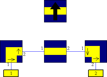
The sub-model is now complete. Note that the rectangular waveguide E-plane corner (TE10) blocks are frequency bounded. Take a look at the Block Properties - General page of one of the E-plane corner blocks inside its property dialog. The frequency bounds for the given (default) properties of this block should be displayed:
7.49481 £ f / GHz £ 16.7589
Because the rectangular waveguide E-plane corner (TE10) blocks are the only frequency bounded blocks inside your model and the parameter sets are identical for both of them, their common frequency bound also represents the valid frequency range for the model.
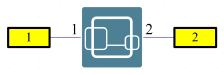
Let us return to the he ’parent’ model’s schematic view. The CST DESIGN STUDIO block now shows two internal ports, as each insertion of an external port inside the sub-model corresponds to an addition of an internal port to the placeholder block. If you remove an external port from the sub-model, the number of internal ports of the CST DESIGN STUDIO block would also be reduced. Now the CST DESIGN STUDIO block inside the ’parent’ model can be connected to two external ports.
Let us now examine the CST DESIGN STUDIO block’s property dialog box. There is no Block Properties - Parameters page, but the initial page is the Block Properties - General page that displays its frequency bounds that exactly correspond to the valid range for the sub-model.

Note that if you provided different frequency unit settings for the ’parent’ model and the sub-model then these values will be scaled according to the units’ ratio, e.g. if ’MHz’ was specified for the ’parent’ model the block’s bounds would be 7494.81 £ f / MHz £ 16758.9.
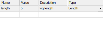
Return to the sub-model now by double-clicking on the block again. Here, we define a parameter ’length’ and assign the value 5 to it. Therefore, simply add the following line to the parameter list control by clicking on the top left cell, entering the parameter’s name and then switching to the next cell using the Tab key. You may optionally specify a description inside the last column of this row. Furthermore, select ’Length’ inside the ’Type’ column. Afterwards, it should look similar to the following image:
Switch to the ’parent’ model now and open the property dialog box of the CST DESIGN STUDIO block (not by a double-click, but by Properties... via the context menu). The Block Properties - Parameters page is shown whose list now contains the sub-model’s parameter ’length’.

Because length was of the ’Length’ type, the units associated with this type may now be chosen for the block’s ’length’ parameter. Therefore, the parameter’s value will be scaled according to the units’ ratio.
Modify the value for ’length’ inside this Block Properties - Parameters page to length=6, choose ’m’ instead of ’mm’ for ’type’ and confirm the change. Then, switch to the sub-model and examine this parameter inside its parameter list control. You will observe that the modification has taken place there, as well: The new value for length is 6000 (mm). Thus, the parameters of the sub-model represent the parameters (properties) of the corresponding CST DESIGN STUDIO block. A modification can either be performed in the block’s ’Parameters’ page or in the sub-model’s parameter list control.
Switch to the ’parent’ model again and define a parameter ’l’ (with an arbitrary value). Assign this parameter ’l’ to the ’length’ property of the CST DESIGN STUDIO block. Now you can use this parameter ’l’ of the model to perform a parameter sweep or an optimization, whereby the parameter ’length’ of the sub-model changes according to ’l’. Note that the parameters could be named the same, but for better distinction we avoided this duplication here.
As previously mentioned, a sub-model can also be exchanged by other CST DESIGN STUDIO™ project files. Therefore, click on the Browse button inside the Block Properties - General page of the CST DESIGN STUDIO block’s property sheet. You can select a CST DESIGN STUDIO™ project file as the new sub-model. If the current sub-model is not empty, CST DESIGN STUDIO™ asks for a confirmation, because all settings and parameters will be overwritten.
See also