Traces
Edit Layout New
Trace
New
Trace
The dialog box is also available via Navigation
Tree: TracesNew
Trace. A right
mouse click on Traces opens a
drop-down menu where the user is able to call the New
Trace dialog box.

Net... /
Layer...: A new trace has to be assigned to a certain net on a
certain layer. In the figure above net (Net0)-1
on layer LYR_1 was selected.
Units: This field allows the
user to select the unit the geometrical entries below should refer to.
After entering the geometry a change of the units inside this field does
not change the geometric size of the trace anymore.
Width: This
field allows the user to assign the width for the trace. The cross-section
of a trace is always assumed to be rectangular. The thickness of the trace
is defined through the definition of the corresponding layer thickness.
For more details see Layers
Stackup.
Points: Inside this field a
flat polygon with an arbitrary number of points can be defined. The tool
bar on right hand side of the field provides five functions:
Create new node
Duplicate selected nodes
Move up (selected node)
Move down (selected node)
Delete selected nodes
Which function belongs to which symbol can be easily determined. Simply
move the mouse pointer over a special symbol and the corresponding function
will be displayed in a small text field. After pressing Ok
the current settings will be accepted.
All traces are stored in Navigation
Tree: Traces. Selecting
a certain trace and performing a right mouse click
opens a drop-down menu where the user is able to call the Edit
dialog box, which is exactly the same dialog as for the generation of
a new trace. In order to edit the trace one simply has to edit the corresponding
entries inside the dialog box. An example of an existing trace to be edited
is shown in the figure below:

Edit
the trace's geometry by mouse: This
second way of editing a trace can be done if the Legacy
Viewer is activated (see Layout
Viewer). If a
certain trace has been selected and the corresponding Edit
Trace dialog box has been opened,
the trace itself will be highlighted in the Main
View as shown in the figure below:
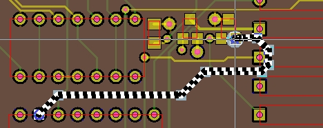
All points that are defined in the point list are
marked and displayed as small squares in light blue color as shown in
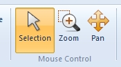
the figure above. After switching the mouse pointer
into the Selection mode with
View: Mouse
ControlSelection
a certain square symbol can be picked and dragged as it was done in
the figure below:

The values of the corresponding point in the point list (inside the
dialog box) will be changed automatically. In order to acknowledge the
new position of the point, the button Apply
has to be pressed.