Cable Library - Cable Groups
Cable Library  Cable Groups
The dialog box is also available via Cable
Navigation Tree: Library
 Cables.
The icons on the top of the dialog box enable actions which are
explained below. The meaning of each icon is also explained by tool-tips.
To see a tool-tip just move the mouse-pointer over the corresponding icon:
 Create a new cable group
 Duplicate a selected coaxial cable
 Import cables from an external Cable
Library File (not restricted to cable groups)
 Export cables into an external Cable
Library File (not restricted to cable groups)
 Remove all cable groups which are not used within
the current project
 Delete the selected cable groups.

Cable groups are the most general cable types supported by CST CABLE
STUDIO. Any kind of cable bundle consisting of single wires, twisted cables,
ribbon cables, and coaxial cables can be created. Furthermore, it is possible
to include cable groups into other cable groups, thus making hierarchical
definition of complex cable structures possible. Cable groups can be wrapped
with insulating or conducting films, they can be cast in different materials,
and the position of each individual wire can be exactly determined or
randomly arranged.
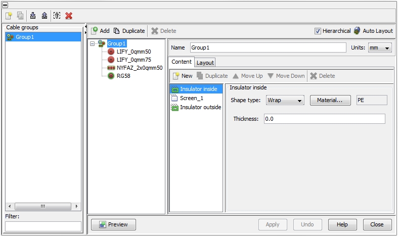
The dialog box contains different frames. All available cable groups
are listed in the Cable groups
frame on the left side.
The tree-like list in the middle frame shows all cables or sub-cable-groups
that belong to the currently selected cable group. Each cable group requires
a unique name that has to be assigned in the field Name
at the top of the right frame. The underlying unit size for geometry
definition can be selected with the Units
pull-down menu. Changing the unit for an existing object does not affect
the size of the cable but just displays the original size in the corresponding
unit. At the top of the right column. If the user clicks on a certain
cable group inside the middle frame the Add button on the top will
be enabled. With this button the user has the possibility to add any kind
of cable from the Cable Library to the
selected cable group. After a cable has been added,
the definition dialog box on the right side will change according to the
needs of the corresponding cable. he user can Duplicate
or Delete an existing cable by
using the corresponding buttons
on the top of the cable list.
If a certain cable group (not an underlying cable) is
selected the parameter definition dialog box on the right shows two further
tabs:
Content tab
The Content tab includes additional
insulators, screens or discontinuous shields that can be defined for the
cable group.
 New: Moving the mouse pointer over this button gets
a pull-down menu where the user can select between three different ypes:
Insulator, Screen
or Discontinuous Shield. According
to the selected type, the corresponding dialog on the right will change
 Duplicate a selected item (Insulator, Screen or Discontinuous
Shield)
 Move an item upwards in the list
 Move an item downwards in the list
 Delete an item from the list.
Layout tab
The Layout tab
presents a tabular view for all cables in the cable group with their distinct
positions and rotation angles. Each cable is situated at a certain x-
and y-position in a local system of coordinates. A positive or negative
rotation angle defines a turn to the left or to the right. The rotation
center is the origin of the system of coordinates in which the dedicated
(just selected) cable was defined. For example, for a single wire the
rotation center is identical to the center of gravity. For arbitrarily
shaped cables or cable groups, however, the rotation center and center
of gravity may differ. At the right top of the dialog box there is the
Auto Layout button which allows
an automatic arrangement of all cables and surrounding materials. When
doing so, the position of each individual cable in the cable group is
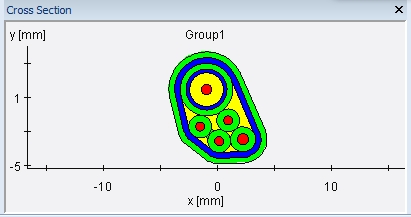
determined in such a way that the resulting cable’s cross-section
is close to a circular area (see figure below). Instead of that, there
is always the possibility of determine the wanted
arrangement manually.

If a cable group contains other cable groups, it is possible to perform
hierarchical arrangements. If the Hierarchical flag at the top
of the dialog box is tagged, all cables in the top cable group and all
further sub cable groups will be automatically arranged after pressing
the Auto Layout button. If the
Hierarchical flag is de-activated,
only the cables in the top cable group will be arranged while keeping
the positions of the cables inside the sub-cable-groups frozen.
Discontinuous
Shields
A discontinuous shield is a screen
which is continuously interrupted by insulating gaps. There is no DC current
path through it and therefore, a discontinuous shield is not handled as
a Signal and no Terminals
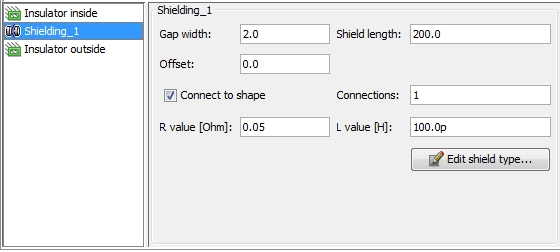
will be derived. The corresponding dialog box is shown in the figure below:

Gap width:
defines the length of the insulating gaps that interrupts the conductive
screen in regular terms
Shield length:
defines the length of the conductive screen segments
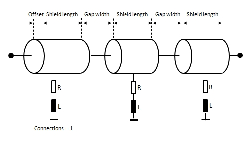
Offset: defines
where the first gap takes place relatively to the Start-Node of the corresponding
Route. The discontinuous shield always begins with a conductive shield
segment and the length of this first segment is "shield
length + offset".
Connect to shape:
defines whether additional connections to an ideal reference conductor
shall be made or not
Connections:
if "Connect to shape" is activated the field defines the number
of connections on every conductive screen segment. The number of connections
will be distributed in an equidistant manner. A single connection is placed
in the center of the screen segments (see figure below).
R value: defines
the resistive value of the connection in Ohm
L value: defines
the inductive value of the connection in Henry


 Cable Groups
 Cables.
The icons on the top of the dialog box enable actions which are
explained below. The meaning of each icon is also explained by tool-tips.
To see a tool-tip just move the mouse-pointer over the corresponding icon:
 Create a new cable group
 Duplicate a selected coaxial cable
 Import cables from an external Cable
Library File (not restricted to cable groups)
 Export cables into an external Cable
Library File (not restricted to cable groups)
 Remove all cable groups which are not used within
the current project
 Delete the selected cable groups.
 New: Moving the mouse pointer over this button gets
a pull-down menu where the user can select between three different ypes:
Insulator, Screen
or Discontinuous Shield. According
to the selected type, the corresponding dialog on the right will change
 Duplicate a selected item (Insulator, Screen or Discontinuous
Shield)
 Move an item upwards in the list
 Move an item downwards in the list
 Delete an item from the list.

