|
微波射频仿真设计 |
|
|
微波射频仿真设计 |
|
| 首页 >> Ansoft Designer >> Ansoft Designer在线帮助文档 |
|
HFSS and Planar EM Simulators > Meshing PropertiesTo assign meshing properties, select one or more objects in the layout editor and click Draw > EM Design Properties > Add Modeling Properties. This assigns meshing-related properties to the object(s) and adds the Modeling Props tab to the Property Window: 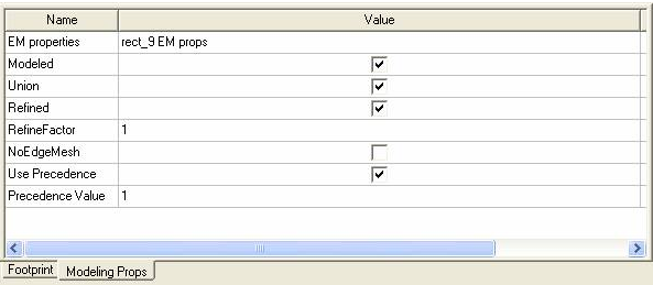 The following controls are available under the Modeling Props tab of the Property window: • Modeled, when checked, specifies that the object is meshed when the circuit is modeled • Union, when checked, specifies that selected objects are unioned when modeled if “Form polygon unions” has been selected in the Planar Setup: Advanced Tab dialog or the HFSS Setup: Advanced Tab dialog. • Refined, when checked, causes the object to be refined. When unchecked, the object will not be refined. • RefineFactor is a positive integer value that specifies the level of refinement. It may also be a variable value. The larger the value, the greater the refinement. A value of one specifies the same refinement relative to other objects. One-half specifies half as much refinement relative to other objects, and two specifies twice as much refinement, and so forth. If a zero value is entered, the Refined box will automatically be unchecked. If a value less than zero is entered, the value will automatically be changed to 1. • NoEdgeMesh, when checked, specifies that no special rectangular-edge mesh is used during modeling. • Use Precedence, when checked, specifies that the mesher will examine the Precedence Value when deciding object precedence. • Precedence Value may be any integer and is used when Use Precendence is checked. Where polygons from different layers/materials overlap, the mesher decides precedence on the basis of Precedence Prioritizing.
Select items one by one in the editor to modify their Modeling Properties in the Property Window. To remove the Modeling Properties tab from the Property Window, click Draw > Remove Modeling Properties.
HFSS视频教程 ADS视频教程 CST视频教程 Ansoft Designer 中文教程 |
|
Copyright © 2006 - 2013 微波EDA网, All Rights Reserved 业务联系:mweda@163.com |
|


