CST MWS共面波端口阻抗和理论计算相差较大的疑问
遇到一个疑问,我用CST2012计算一个共面波导的端口阻抗,我把共面波导的参数按照下面的图1中的数据设计的,
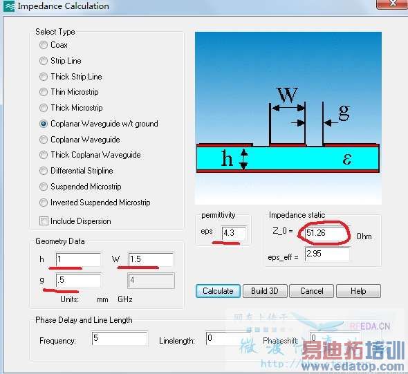
图1
按照软件计算出来的,阻抗应51.26.
接着我采用波端口作为激励,设置端口大小(端口宽7.5,高2.5)为图2:
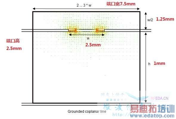
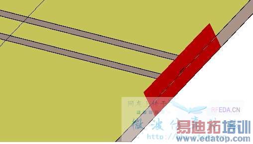
图2
但是计算出来的线阻抗(line impendence) 只有24点多,如图3
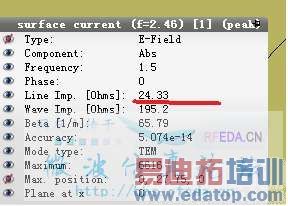
ps:缝隙0.5mm,已经用加密至五个网格了,为什么端口阻抗(线阻抗)和理论计算的差别那么大呢?
附上模型:
楼主为什么要选定Free normal position这个选项?
Free normal position: Please activate this button to define an internal port, i.e. a port location inside the calculation domain. This check button is only enabled for a Free or Full plane transversal range setting (see above).
The value for the normal position can be inserted in the correspondingX/Y/Zpos text field. If the value exceeds the dimension of the calculation domain, the port will be snapped to the boundary of the calculation domain.
Note: Deactivating this button will always locate the port on the lower or upper boundary of the calculation domain, corresponding to the definition of the lower or upper port orientation.
建议楼主把这一项取消,就会得到比较相近的结果。
另外,cst中的宏计算器计算阻抗是使用近似公式,全波场仿真结果更准确些。
前面正解---宏计算仅仅是近似而已,具体还得通过端口计算来调整
因为,我要使用这个共面波导既作为传输线,又作为天线的地板,
是这样的,激励和天线分别在共面的波导两侧,
我又看这个天线的远场图,必然要将各个方向上的边界条件设置设置成open或者open(add space),这样就增加了计算区域,
如果我不使用Free normal position将激励调整到原来的位置(即共面波导的入口出),很明显这个波端口就要建立在边界条件一个面处。这样激励很明显是在边界处开始,在真空的面(介质)中的一个波端口激励,
另外,我用宏计算只是计算一下大概的线宽,缝隙和介质及高度的尺寸,只要保证共面波导为50Ohm左右的特性阻抗。
你说的也是把Free normal position去掉吗?这个我知道,宏计算是近似,更精确是要端口计算调整。
楼主的要求是这样啊,那么应该这么办,先看帮助文件怎么说:
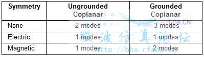
If no symmetry condition is defined in the middle of the coplanar line, both even and odd modes can exist and therefore need to be taken into account. If an electric symmetry condition is specified, only the odd mode can exist. On the other hand, setting a magnetic symmetry condition will consider the even mode only.
If the microstrip line is grounded, another parasitic microstrip mode will exist too as long as no electric symmetry is defined. All this leads us to the following table for the number of modes normally used for the simulation at the coplanar port:
Note that the order in which the port modes are calculated may vary depending on the dimensions of the structure as well as the frequency. Therefore we highly recommend always inspecting the port mode results in order to avoid misinterpreting the S-parameter data.
因此楼主看的是第一个模式,没有看到真正的奇偶模分布。所以得到的阻抗也就不是真正想看的阻抗了。
Another important aspect in the simulation of coplanar lines is the fact that the mode pattern is frequency dependent (unlike the mode patterns in empty guides or coaxial lines).
The frequency domain solvers automatically recalculate the mode patterns for every frequency point so that this frequency dependency does not constitute a difficulty for analysis.
In contrast, the time domain solver uses the same mode pattern for the entire frequency band which may cause port mode mismatches at frequencies other than the mode calculation frequency. The error increases with increasing distance to the mode calculation frequency.
因此使用时域求解器计算多模问题时要特别注意。
的确是,接地的共面波导,在无对称的电壁和磁壁下,有三种传输模式,我只仿真了其中的一个模式,而且共面线模式的场型是色散的,时域求解器在整个频带上使用同一模式的场型,肯定会在某些频带失配,时域的求解器不适合共面线的仿真