|
微波射频仿真设计 |
|
|
微波射频仿真设计 |
|
| 首页 >> Ansoft Designer >> Ansoft Designer在线帮助文档 |
|
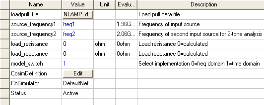
Nexxim Design Examples > Power Sweep using Time Domain ImplementationFor most analyses, the newer frequency domain implementation produces much the same result as the earlier time domain implementation. In the case of the powersweep, there is a noticeable difference. 1. Select the NLAMP element and open its Properties.
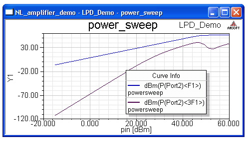
Set the model_switch property to 1 to select the time domain implementation. Click OK to close the Properties window. 2. With analysis powersweep still selected, right-click and select Analyze. The analysis runs to completion. 3. Click on the Results icon and double click on powersweep to see the results:
The powersweep plot shows the fundamental (red) and third harmonic (blue) output power plotted vs. input power pin. Here we can see the saturation of the amplifier. In the linear region the fundamental output power has a slope of 1:1 while the third harmonic has a slope of 3:1 vs. the input power. Both scales \are in logarithmic units (dBm). Notice the notch at the upper end of the 3F1 trace. This feature is missing from the frequency domain plot.
When you have finished viewing the reports, you may save the project.
HFSS视频教程 ADS视频教程 CST视频教程 Ansoft Designer 中文教程 |
|
Copyright © 2006 - 2013 微波EDA网, All Rights Reserved 业务联系:mweda@163.com |
|