|
微波射频仿真设计 |
|
|
微波射频仿真设计 |
|
| 首页 >> Ansoft Designer >> Ansoft Designer在线帮助文档 |
|
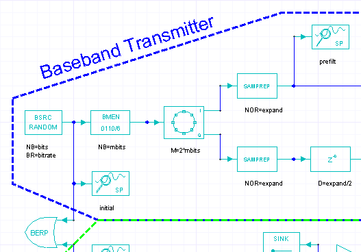
Nexxim Design Examples > Baseband Transmitter SchematicThe baseband transmitter is at the upper left of the schematic. The baseband transmitter stage takes an input bit stream, encodes it into symbols, converts the symbols using QPSK and I/Q modulation, and outputs the modulated signal upshifted in frequency. Here is the left side of the Baseband transmitter schematic:
This part of the Baseband transmitter contains the following elements from the System simulator component library: • A pseudorandom source. The pseudorandom data set is a good approximation to a compressed set of transmission data. The number of bits to be generated (NB) is set to the parameter bits=1024. The bitrate (BR) is set to the parameter bitrate=2000000 (2MHz). • A Binary-to-M-ary encoder. The number of bits to group into one symbol (NB) is set to the parameter nbits=2. The bitstream will be encoded into four symbols: 0, 1, 2, and 3. • A phase-shift keying modulator. The order M is set to 2^nbits=4, or QPSK. This element divides the signal into its real and imaginary parts, so now we have two parallel signal paths. • Symbol repeaters on both paths. The number of repeats is set to parameter expand=8. The sampling rateis likewise multiplied by 8. Oversampling makes the waveform appear more continuous to the time domain simulator. • A delay element on the lower path, adding a delay of expand/2=4 symbols to the imaginary data. • A system probe, prefilt, is inserted to enable you to view the real part of the signal at this point. Here is the right side of the Baseband Transmitter schematic:
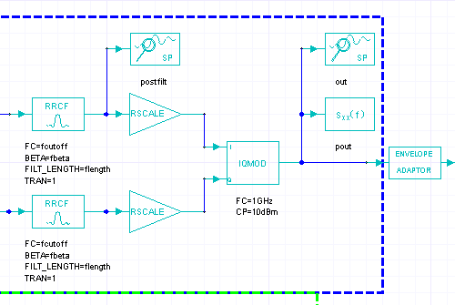
This part of the Bseband transmitter contains the following elements from the System simulator component library: • Root raised cosine filters on both real and imaginary data paths. The cutoff frequency for both filters is set to parameter fcutoff=4MHz. The rolloff factor BETA is set to parameter fbeta=0.35. The number of filter coefficients FILT_LENGTH is set to parameter flength=64. • A system probe, postfilt, is inserted to enable you to view the real part of the signal at this point. • Real signal scaling elements on both paths. These are provided to enable you to experiment with real and imaginary signals with different gains. The gain on both elements is set to 1. • An IQ modulator that receives the real part of the signal on input I (In-phase) and the imaginary part on input Q (Quadrature phase).The IQ modulator combines the signals and upshifts the output. The carrier frequency FC is set to 1GHz andthe carrier power CP is set to 10dBm. • A system probe, out, is inserted to enable you to view the signal as it leaves the Baseband transmitter. • A power spectral density probe, pout, is inserted to enable you to view the power output of the Baseband transmitter. • An Envelope adaptor. The adaptor is required to connect the Baseband transmitter stage, with only behavioral components, to the RF transmitter stage which includes electrical components. Behavioral components are unidirectional and time-based; the output is a function only of the input. Electrical components are bidirectional and frequency-based; reflections at both input and output can be characterized with S-parameters. The Envelope adaptor identifies the waveform as an envelope to the the Nexxim portion of the simulation. The Nexxim simulation then knows to send on an envelope waveform.
HFSS视频教程 ADS视频教程 CST视频教程 Ansoft Designer 中文教程 |
|
Copyright © 2006 - 2013 微波EDA网, All Rights Reserved 业务联系:mweda@163.com |
|