|
微波射频仿真设计 |
|
|
微波射频仿真设计 |
|
| 首页 >> Ansoft Designer >> Ansoft Designer在线帮助文档 |
|
Filter Design Tool > Replacing an InverterImpedance inverters are one of the foundations for microwave filters. Not only they are ideal and they represent frequency-independent coupling between various resonators, but they also can be used as impedance transforming sections.
Impedance inverters are truly hypothetical elements, so unless you are using them as a coupling mechanism between coupled line structures, you should convert them into equivalent circuits in order to realize them. An impedance inverter can be replaced with any lossless impedance Pi or Tee section. The values of elements are found by calculating an impedance at a given frequency and making it equal to K, the inverter constant.
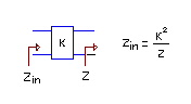
This equivalency holds only at a given frequency. However, most of the applications are bandpass filter designs and they require a whole band to be closely approximated. Although center frequency seems like a good candidate to perform the approximation, this sometimes yields in-band resonances. Filter Design Tool interprets passband corners (fp1 and fp2) in a slightly different manner than center frequency approach which gives good results for narrowband filters. You can change these frequency variables in the Transformation Settings dialog box. An impedance inverter can also be replaced with a quarter-wavelength transmission line, with characteristic impedance Zo being K.
To replace an impedance inverter with an equivalent circuit: 1. Select an inverter. 2. Click Replace Inverter on the Filter>Transform submenu. 3. In the Transformation Settings dialog box, select the circuit you want to replace with. 4. Click OK.
HFSS视频教程 ADS视频教程 CST视频教程 Ansoft Designer 中文教程 |
|
Copyright © 2006 - 2013 微波EDA网, All Rights Reserved 业务联系:mweda@163.com |
|