|
微波射频仿真设计 |
|
|
微波射频仿真设计 |
|
| 首页 >> Ansoft Designer >> Ansoft Designer在线帮助文档 |
|
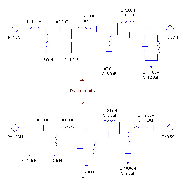
Filter Design Tool > Obtaining a Dual CircuitDue to the selection of the -/+ sign of S11 during the element extraction stage of the filter synthesis, there are usually two alternative circuits, one of which is called the dual of the other. For example, if you replace all series inductors with shunt capacitors and all shunt capacitors with series inductors retaining their original normalized values in an odd-order lowpass filter, you obtain the dual of the original circuit. Extending this discussion to resonators, distributed stubs, and inverters, one can find a dual circuit for almost every circuit. Note that the dual circuit logic still holds for even-order filters or filters having unequal terminations. In this case, the load terminations are set to Ro’ = Rs*Rs / Ro to have the same frequency response. In all cases, when dual circuit is requested, the filter is first normalized to Rs = 1.0. Then all elements are replaced with their dual and the circuit is renormalized back to original source value. A dual circuit is an exact equivalent of the original circuit, so forming a dual circuit does not change the electrical behavior and you do not lose any precision. Performing two dual operations on a circuit will return to the original circuit.
To obtain the dual circuit: Click Dual on the Filter>Circuit submenu.
HFSS视频教程 ADS视频教程 CST视频教程 Ansoft Designer 中文教程 |
|
Copyright © 2006 - 2013 微波EDA网, All Rights Reserved 业务联系:mweda@163.com |
|


