![]()
![]()
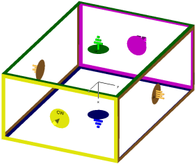
Due to the fact that a computer is only capable of calculating problems that have finite expansion, you need to specify the boundary conditions. This can be done within this dialog box.When you enter the boundaries property sheet, the modeled structure is displayed with a surrounding bounding box colored with regard to the boundary condition at each boundary. The picture on the right shows an example of such a bounding box.The assignment of the colors to the boundary conditions is listed together with the description of the different boundary conditions below. |
|
You may double-click on the boundary conditions icon in the main plot window to select one boundary. By pressing the right mouse button in the main plot window, you can set the type of the boundary condition for the selected boundary using the popup menu.
Boundary conditions : Xmin / Xmax / Ymin / Ymax / Zmin / Zmax
Several boundary types are available, each applicable to any face of the project's bounding box (xmin/xmax/ymin/ymax/zmin/zmax).
|
Electric: Operates like a perfect electric conductor: all tangential electric fields and normal magnetic fluxes are set to zero.
|
|
|
Magnetic: Operates like a perfect magnetic conductor: all tangential magnetic fields and normal electric fluxes are set to zero.
|
|
|
Open (PML): Operates like free space: waves can pass this boundary with minimal reflections. Note that in case of a unit cell simulation with the general purpose frequency domain solver open boundaries are realized by a Floquet port.
|
|
|
Open (add space): Same as Open (PML), but adds some extra space for farfield calculation. This option is recommended for antenna problems.
|
|
|
Periodic: Connects two opposite boundaries with a definable phase shift such that the calculation domain is simulated to be periodically expanded in the corresponding direction. Thus, changing one boundary to periodic always changes the opposite boundary to periodic as well. If you select a periodic boundary condition you may enter a phase shift for this boundary in the Phase Shift/Scan Angle property page. Simulating antenna models with periodic boundaries enables you to examine the near field influence among the individual antennas. However, note that the resulting structure represents an infinitely extended antenna pattern. Hence the farfield results are most accurate in conjunction with the definition of an (preferably large) antenna array in the farfield postprocessing. Please refer to the farfield overview for details. |
|
|
Conducting Wall: This boundary behaves like a wall of lossy metal material. |
|
|
Unit Cell: A Unit Cell boundary condition is very similar to the Periodic boundary condition. In addition, a two-dimensional periodicity other than one in the direction of the coordinate axes can be defined (Boundary Conditions - Unit Cell). If there are open boundaries perpendicular to the Unit Cell boundaries, they are realized by Floquet modes, similar to modes of a wave guide port . The farfield considerations are the same as for the periodic boundaries. |
|
Open boundary...
This button leads to a dialog box, where you can define special settings for the chosen open boundary condition. For a regular PML, it would be the Settings for PML boundary dialog box.
Floquet Boundaries...
For a unit cell, the open boundary condition is realized by a Floquet port. This button is displayed instead of the button Open boundary... if unit cell boundaries conditions are selected, and enabled if the boundary condition for Zmin or Zmax is set to open. Pressing this button opens the Settings for Floquet Boundaries dialog.
OK
Accepts your settings and leaves the dialog box.
Cancel
Closes this dialog box without performing any further action.
Help
Shows this help text.
See also
Frequency Domain Solver, Eigenmode Solver, Transient Solver
Boundary Conditions: Symmetry Planes, Phase Shift/Scan Angle, Unit Cell, Boundary Temperature, Thermal Boundaries
Settings for PML Boundary, Settings for Floquet Boundary


HFSS视频教程 ADS视频教程 CST视频教程 Ansoft Designer 中文教程
|
Copyright © 2006 - 2013 微波EDA网, All Rights Reserved 业务联系:mweda@163.com |
|