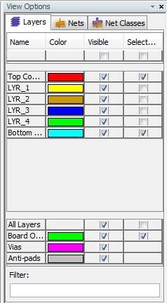
View Options Window
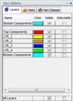
A central tool for manipulating the view on the PCB is the Attribute
Manager inside the View Options
window as shown in the figure below. The dialog box consists of three
different tabs where three important view characteristics of the Layers, Nets
and Net Classes can be edited.
The default tab is Layers. All
tabs are organized in the same kind of table.
The three view characteristics are Color,
Visible and Selectable
and they can be defined in the corresponding columns of each tab. The
rows are filled with the corresponding list of layers (in the tab Layers), with the corresponding list
of nets (in the tab Nets) and
with the corresponding list of net classes (in the tab Net
Classes).
Color: The
Attribute Manager allows the
user to assign special colors to every layer in the tab Layers,
to every net in the tab Nets
and to every net class in the tab
Net Classes. In addition, a standard color can be assigned to the
Board Outline,
to Vias and to Anti-Pads.
The Main View can only display
one color scheme at a time. The color scheme which should to be used can
be chosen with the help of the Color
Mode function (see Color
Mode function).
This allows a clear investigation of a complex PCB with many layers
and nets. For instance, if one is interested in how certain nets are spread
over various layers, it is useful to switch the Color
Mode to Nets and to choose
the Layers
tab in the View Options window.
Then, by selecting the different layers one by one, you can easily trace
the nets by their corresponding colors.
Visible: The
Visible flag defines whether
a structure (layer, net, net class)
will be displayed in the Main View
or not.
Selectable:
The Selectable flag defines whether
a structure (layer, net, net class)
can be selected in the Main View
or not (see Navigation
Tree and Selection Manager).
Adjusting column size
Because of less space inside the dialog box, it can happen that the
names in the column Name (names
for either layers, nets or net classes) aren't fully displayed. This is
due to the default settings which force the dialog box to divide the available
space for all columns (Name,
Color, Visible,
Selectable) equally.
In order to expand the column Name
to the full size for each entry, the user has to click inside the field
Name, call the corresponding
drop-down-menu by a right-mouse-click
and select Auto Fit Columns Size
(or Fit Columns Size). The result
is shown below:
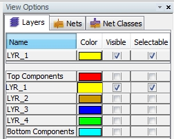
Activating different entries
In order to switch single entries ( e.g. a special layer in the Layers tab) on or off, the user has
to select the corresponding entry in the column Name
with the left mouse button. The selected entry will be tagged as Visible and Selectable
while all other entries will be de-activated as shown in the figure below:
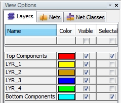
In order to activate all entries at the same time, the user has to
select the button at the bottom of the dialog box. In case of the
Layers tab,
the button is called All Layers. With the help
of this button, the choice for Visible
or Selectable is assigned to
all entries, as shown in the figure below:
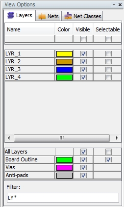
Filter entries
Filtering a special group of entries can be very helpful when dealing
with a huge board consisting of many layers and many nets. This can be
done by entering a special string inside the Filter
field as shown in the figure below: