Create a Cone
 Shapes
 Cone Cone
In this dialog box you may specify the dimensions of a cone either
numerically or by using .
The construction will always be performed in the currently active .
Each cone will be assigned to a particular material
in which all shapes will share the same material properties and colors.
The new cone is also associated to a certain component and is identified
by a unique
within this component. The shape can be addressed by this name
for subsequent editing operations.
As soon as the shape is defined it will appear in the
and beneath the associated component in the
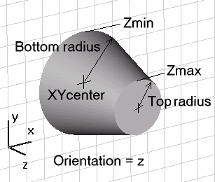
The picture below shows a cone defined in global coordinates:

Name
Specify the unique
for the cone.
Orientation: X/Y/Z/U/V/W
Specify the orientation of the cone’s
axis along the currently active coordinate system. The axis must always
be aligned with one of the coordinate axes. To define a cone axis which
is not parallel to one of the coordinate axes you have to specify a
for which one of its axes points into the desired direction.
According to the currently active coordinate
system only either X/Y/Z (global coordinates) or U/V/W (local coordinates)
will be shown in the dialog box.
Bottom radius
Specify a valid
for the bottom radius of the cone (at the lower end of the orientation
coordinate axis range).
Top radius
Specify a valid
for the top radius of the cone (at the upper end of the orientation coordinate
axis range).. This setting may either be zero for a complete cone or nonzero
for a truncated cone.
Xcenter, Ycenter, Zcenter
Specify valid
for the center coordinates of the cone base in the global coordinate system
perpendicular to the cone axis. According to the orientation, only two
of these entries will appear in the dialog box. Please note that these
entries only appear when the global coordinate system is currently active.
Xmin, Ymin, Zmin, Xmax, Ymax, Zmax
Specify valid
for the start and end coordinates of the cone along the orientation of
the cone axis. According to the orientation only one pair of these settings
(Xmin/Xmax, Ymin/Ymax or Zmin/Zmax) will be shown in the dialog box. Please
note that these entries only appear when the global coordinate system
is currently active
Ucenter, Vcenter, Wcenter
Specify valid
for the center coordinates of the cone base in the local coordinate system
perpendicular to the cone axis. According to the orientation, only two
of these entries will appear in the dialog box. Please note that these
entries only appear when a local coordinate system is currently active.
Umin, Vmin, Wmin, Umax, Vmax, Wmax
Specify valid
for the start and end coordinates of the cone along the orientation of
the cone axis. According to the orientation only one pair of these settings
(Umin/Umax, Vmin/Vmax or Wmin/Wmax) will be shown in the dialog box. Please
note that these entries only appear when a local coordinate system is
currently active
Segments
Specify a valid integer expression for the segmentation
of the cone. The bottom and top (if top radius is not zero) will be divided
into the specified number.
Component
Choose a new
from the select list. You can also create a new component by typing the
name of the new component.
Material
Select the material
to which this shape will be assigned from the list of previously defined
materials or create a new material by selecting [New
Material...]. You can also load a material from the material library
by selecting [Load from Material Library...].
OK
Press this button to finally create the cone.
Preview
Press this button to create a preview image
of the cone. This option is very useful to check the settings before you
actually create the shape.
Cancel
Closes this dialog box without performing any
further action.
Help
Shows this help text.
See also
Brick,
Sphere, Cylinder,
Elliptical cylinder, Torus,
Analytical
Face, Extrude Profile,
Extrude Face, Rotate
Profile, Rotate Face,
Loft, Shell,
Coordinate systems,
Bond Wire.


HFSS视频教程
ADS视频教程
CST视频教程
Ansoft Designer 中文教程
|