Face Constraints
 Modeling:
Tools
Modeling:
Tools Modify LocallyDefine Face Constraints... Modify LocallyDefine Face Constraints...
In this mode, you may define constraints of picked faces. Those are
properties of faces like a distance to other geometry or a radius of a
cylindrical face.
To satisfy the constraint, local modifications
are applied to the face(s) when you press 'Apply' or 'OK' (For a general
description, check Face
Modifications). If you continue modeling, it is not
assured that these constraints
stay valid.
You may remove defined face constraints in the Show
Face Constraints dialog.
Note: This
mode is intended for defining parameters that are to be used with sensitivity
analysis (see Sensitivity
Analysis Overview for more information). But it can also be useful
for common modeling, to have an alternative way to define local modifications.
Continuing modeling on a shape with constraints attached will invalidate
the constraints. Therefore, it is recommended to apply constraints that
should be used with Sensitivity Analysis at the very end of the modeling
process.
There are three types of face constraints:
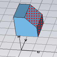
Set distance to plane
Of all picked faces, a bounding box is calculated.
The center of this bounding box is used to define a distance to one of
the three principal planes.
You may use the arrows to drag the bounding box
around by mouse, or change the distance (and plane normal) in the dialog.
To define a distance to an arbitrary plane, position the local coordinate
system (WCS) to your likeness.
|
|
|
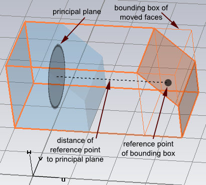
Example:
We set the distance of the picked faces to the U plane to be 3 units.
To measure the distance, the bounding box of the two picked faces is used.
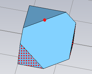
Set distance to point
We define the distance of a point to a
planar face as the smallest distance to the plane that defines
the surface of the planar face.
For every picked planar face, the distance to a
base point is set to the given
value. After this operation, all faces have the same distance to that
point.
The base point is initialized as pick, if point
picks exist, or the center of the last picked planar face is taken (that
implies, that the initial distance of that face to the base point is zero).
The dialog provides the possibility to set an arbitrary base point.
You may drag one of the picked faces around or use
the dialog to specify the distance to the base point.
|
|
|
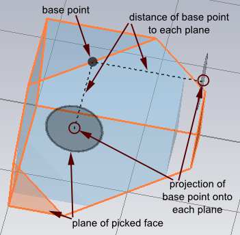
Example:
We set the distance of the two picked faces to the picked base point to
1 unit. The projection of the base point onto the picked planar faces
plane doesn't have to be onto the face area (as indicated by the gray
discs).
Set radius
All picked cylindrical faces are set to the entered
radius. You may change the value by dragging the faces or entering a new
radius.
Note: If you use the mouse
to define a constraint on tiny details, snapping (rounding the constraint
value) might become a problem. In that case, adjust the working plane
settings in the Working
Plane Properties dialog
Consider blends is
explained in the article for Face
Modifications.
Parametrize
You may set the new value (distance or radius) to
a new parameter by simply clicking the Parametrize
button. This is needed for the Sensitivity Analysis.
Sensitivity / Yield analysis
Parameters defined within this mode are valid for
sensitivity analysis (as long as they are not used in any invalid operation)
See also
Face Modifications, Show
Face Constraints, Sensitivity
Analysis Overview, Yield
Analysis Overview


HFSS视频教程
ADS视频教程
CST视频教程
Ansoft Designer 中文教程
|
