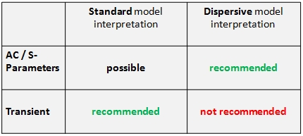

The dispersive model interpretation inside the circuit simulator means the equivalent circuit of the cable will not be directly integrated in the overall circuit. Instead of this, its frequency dependent behavior will be sampled on the terminals within a separate pre-precessing phase (from DC up to the specified Maximum valid frequency). In the actual circuit simulation only this frequency based terminal behavior will be considered. The most significant advantage of this method is its model order reduction. A further advantage is its possibility of using precise analytic formula to describe the frequency dependent losses, no approximation has to be made (see Ohmic loss modeling or Dielectric loss modeling). A disadvantages of the method is the pre-processing step which can afford more time than the overall simulation with the standard model interpretation. In addition, this method should only be used if the number of terminals is low (a limit may be 10). Further on, the method should only be used within the frequency domain (AC- or S-Parameters task). For Transient tasks it may lead to less accurate results.
The following table shows the recommended usage of both methods:

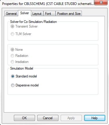
In order to decide which model interpretation should be used, the user has to right mouse click on the schematic symbol and choose Properties from the pull-down menu. A dialog will appear where the tab Layout has to be selected:
