Cable Library - Ribbon Cables
Cable Library  Ribbon Cables
The dialog box is also available via Cable
Navigation Tree: Library
 Cables.
The icons on the top of the dialog box enable actions which are
explained below. The meaning of each icon is also explained by tool-tips.
To see a tool-tip just move the mouse-pointer over the corresponding icon:
 Create a new ribbon cable
 Duplicate a selected ribbon cable
 Import cables from an external Cable
Library File (not restricted to ribbon cables)
 Export cables into an external Cable
Library File (not restricted to ribbon cables)
 Remove all ribbon cables which are not used within
the current project
 Delete the selected ribbon cables.

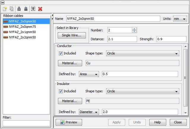
All available Ribbon cables
are listed in the column on the left side of the dialog box. When selecting
an item in the list the corresponding definition is shown on the right
side. Each cable requires a unique name that has to be assigned in the
field Name. The underlying unit
size for geometry definition can be selected with the Units
pull-down menu. Changing the unit for an existing object does not affect
the size of the cable but just displays the original size in the corresponding
unit.
Ribbon cables are an array of single wires with a certain distance
in between (the definition is similar to the definition for Twisted
cables.) The corresponding geometrical and electrical parameters of
the basic single wire can be either entered directly (using the frames
Conductor- and Insulator
frames) or easily obtained by pressing the Single Wire button
inside the frame "Select in Library".
The number of single wires to be used for the ribbon
cable can be specified inside the Number
field. Their mutual distance can be defined in the Distance
field. The single wires are linked by an insulator material that is identical
to the defined single wires’ insulator. The particular strength
of this link can be specified in the Strength field.
The Preview button enables
the display of the selected single wire in the Cross
Section View window. The Undo
button enables to undo any changes. When pressing the Apply button,
however, all data will be updated in CST CABLE STUDIO and the Undo
button will be automatically disabled then.
NOTE:
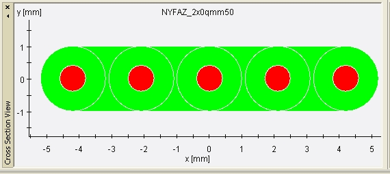
The linking insulator’s strength must be bigger
than zero; otherwise you will be prompted with an error message. If you
define a strength that exceeds the maximum expansion of the single wires
then the wires will be just embedded into this insulator as can be seen
in the figure view below:


 Ribbon Cables
 Cables.
The icons on the top of the dialog box enable actions which are
explained below. The meaning of each icon is also explained by tool-tips.
To see a tool-tip just move the mouse-pointer over the corresponding icon:
 Create a new ribbon cable
 Duplicate a selected ribbon cable
 Import cables from an external Cable
Library File (not restricted to ribbon cables)
 Export cables into an external Cable
Library File (not restricted to ribbon cables)
 Remove all ribbon cables which are not used within
the current project
 Delete the selected ribbon cables.
