Cross Section View Features
By default, the Cross Section View
window is placed below the Main View window. This chapter explains
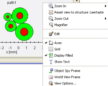
the visualization features provided by the context menu (via right-mouse-click)).
In general, the Cross Section View
visualizes the 2D cross sections of the cable segments.

Zoom In: Allows
to zoom in by discrete factors
Reset view to structure:
Allows to set the view to its initial default settings
Zoom Out:
Allows to zoom out by discrete factors
Magnifier:
Allows to have a closer look on details of the cross section
Edit: Opens
the Edit
Route dialog box of the corresponding route
Axes: enables
to turn on/off the axes of the coordinate system:
Grid: if the
axes are activated an additional feature allows to turn on/off the display
of a grid
Display Filled:
the user can decide whether the cables should be
completely colored or not:
Show Text:
enables to turn on/off the signal names of the related to the wires
Object Spy:
enables to browse over the cross section with the left mouse button and
information on cable details are given in a separate small window
World View Frame:
if zoomed into a cross section the World
View Frame gives orientation
where the user is currently looking at. The information is shown in a
separate small window. The green frame is the symbol for the overall size
of the structure. The red frame shows on what part of the structure the
user is currently looking at in the
Cross Section View.
View Options...
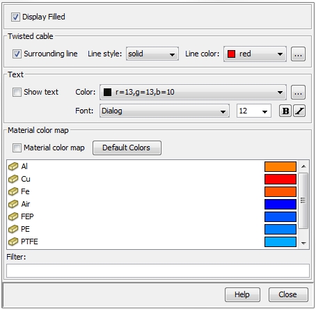
After selecting View Options
a dialog box will appear allowing the definition of special visualization
characteristics:
Display
Filled: the field allows to decide whether the wires in the bundle
should be completely colored or not (see above).
Twisted Cable:
a twisted cable is a cable that changes its cross section along its length
according to its twist per meter.
In order to show the whole space consumption inside the Cross
Section View a help-line
can be displayed. By activating/de-activating the Surrounding
Line check button this help-line
can be turned on/off. The fields Line
Style and Line Color allow
the visual representation of this line.
Text: the
field allows to decide whether the signal names of the wires should be
displayed or not. The fields Color
and Font allow the definition
of the font type, the font
color and the font size.
Material Color Map:
allows to define special colors for each material defined in the Material
Library (Material
Library).


