|
微波射频仿真设计 |
|
|
微波射频仿真设计 |
|
| 首页 >> Ansoft Designer >> Ansoft Designer在线帮助文档 |
|
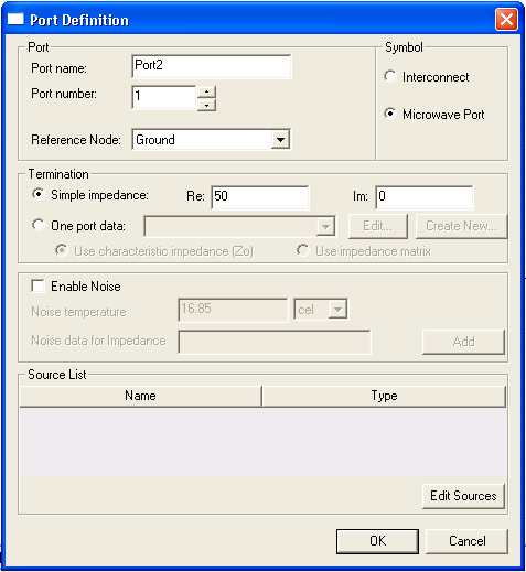
Schematic Editor > Editing an Interface Port DefinitionTo edit the definition of an interface port, right-click the port symbol and select Edit Port from the menu. The Port Definition dialog opens:
Port Name and Number Use the Port name and Port number fields to rename and renumber the port as desired. The node to which the port is attached will change to match the specified port name. Use the Reference Node pulldown to select from the existing ports the one to be used as a common reference node for all sources attached to this port; the default is Ground.
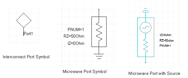
Interface Port Symbol The default symbol for an interface port is a diamond. Optionally, you can choose a more complex symbol to represent a microwave port: • To select a new Microwave port symbol, click its radio button in the Symbol panel of the Port Definition dialog box. The symbol indicates when a source is enabled for that port. • To restore the default symbol, click the Interconnect radio button. The definition of the port remains the same for both symbols.
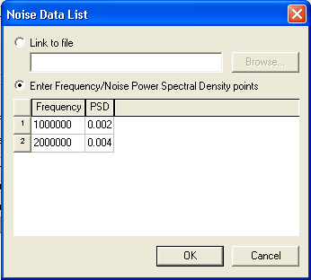
Interface Port Termination Use the Termination panel to control the termination to the port. • With Simple termination selected, you can set the real (Re) and imaginary (Im) parts of the port impedance. The default impedance is 50 ohms for the real part and 0 ohms for the imaginary part. • With One port data selected, use Edit or Create New to edit a one-port device or create a new one. With Nexxim, you can then choose between Use characteristic impedance (Zo) or Use impedance matrix. For more information see N-Ports in Designer. Interface Port Noise Data In Nexxim only, you can specify noise data for the interface port. Click the checkbox Enable Noise. The Noise Temperature and Noise Data for Impedance fields are activated. • The default for Noise Temperature is 16.85× Celsius. Enter a new temperature as desired. • To add Noise Data for Impedance, click the Add button. The Noise Data List dialog opens:
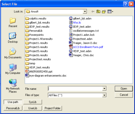
The default selection is Link to File. To use data from a file of noise data, use the browse button to open the Select File dialog:
Noise data files have the format. The frequencies are in Hz and the corresponding noise power spectral densities are in Amp2/Hz. #Hz freqn psdn • Use the Look in field to specify a directory, or locate the file by clicking Use Path, PersonalLib, UserLib, or SysLib. • Within the folder, select the file from those listed, or type the name of the file in the File Name box. • If you select Use path, type the name of the file in the File Name box, or use the Look in field to navigate to the file and record its name. Note that components or libraries imported with Use Path may not be portable when the project is moved to another machine. • When the In project folder button is selected, references to the file in the design are relative to the directory where the project resides. In this case, the path is saved in the project .adsn file as a variable such as: .lib '$PROJECTDIR/x_113854.lib' • The variable $PROJECTDIR will be expanded to the current location of the project when the design is converted to a netlist and run by an analysis tool. Otherwise, an absolute path is saved. If you move a project and its library files together to a new directory, you can preserve the file references by selecting the Project Folder option. • To enter the noise data directly, click Enter Frequency/Noise Power Spectral Density points. Enter the frequencies (in Hz) and the corresponding PSDs (in Amp2/Hz). Use the Tab key to advance to the next field. When all the noise data are as desired, click OK to close the Noise Data List dialog and return to the Port Definition dialog. Click OK to complete the port definition and close the dialog.
HFSS视频教程 ADS视频教程 CST视频教程 Ansoft Designer 中文教程 |
|
Copyright © 2006 - 2013 微波EDA网, All Rights Reserved 业务联系:mweda@163.com |
|