|
微波射频仿真设计 |
|
|
微波射频仿真设计 |
|
| 首页 >> Ansoft Designer >> Ansoft Designer在线帮助文档 |
|
Nexxim Simulator > AMI Source
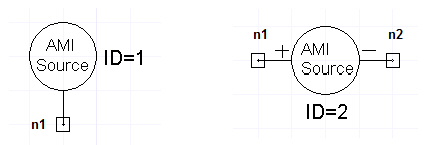
AMI Source Netlist FormatAn AMI source is required for IBIS Application Modeling Interface Analysis. Single-ended and differential versions are available. The netlist syntax for the AMI Source is: AAMISOURCExxxx n1 [n2]
COMPONENT=AMI_SOURCE n1 is the node connected to the single-ended source. n1 and n2 are the positive and negative nodes connected to the differential source. The differential AMI source must be connected between two signal lines. Neither node should be directly grounded. See Notes below for details. The entry COMPONENT=AMI_SOURCE is required.
AMI Source Netlist ExampleAAMISOURCE3 Port1 Port2 COMPONENT=AMI_SOURCE To run examples of AMI analysis, see AMI Analysis Example in the Getting Started Guide. Notes1. The Single-Ended AMI source has the generalized internal structure below:
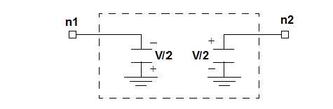
The internal voltage source amplitude is set by VHIGH and VLOW. The source is grounded internally. 2. The Differential AMI source has the generalized internal structure below:
Each of the two nodes is driven with half the voltage amplitude of the single-ended source and opposite polarity. The output is symmetrical in that the average of the two outputs is close to zero. The series resistance is also divided equally between the two nodes. Both sources are internally grounded. 3. The Single-Ended AMI source connects to a signal line. The line should not be directly grounded. The corresponding AMI probe should connect to the same signal line without any direct ground connection. 4. The Differential AMI source connects to two signal lines. Neither node should be grounded. The corresponding Differential AMI probe should connect to the same two signal lines without direct grounding.
HFSS视频教程 ADS视频教程 CST视频教程 Ansoft Designer 中文教程 |
|
Copyright © 2006 - 2013 微波EDA网, All Rights Reserved 业务联系:mweda@163.com |
|