|
微波射频仿真设计 |
|
|
微波射频仿真设计 |
|
| 首页 >> Ansoft Designer >> Ansoft Designer在线帮助文档 |
|
Nexxim Simulator > IBIS AMI Model SupportNexxim supports the import of IBIS AMI models via an import wizard. To open the wizard, select Import AMI Components from the Tools menu:
The Select File for AMI Component dialog opens:
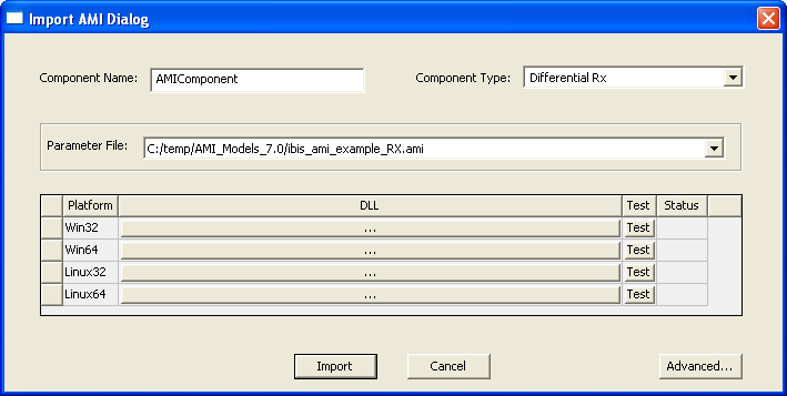
Select the type of file, AMI file (*.ami). Browse to the directory containing the AMI files. Click OK. The Import AMI Dialog opens:
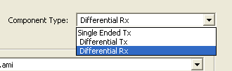
Use the Component Type pulldown to select the type of component to be created:
Use the DLLs pulldowns to select a library by platform:
Clicking on a DLL button opens the corresponding select dialog:
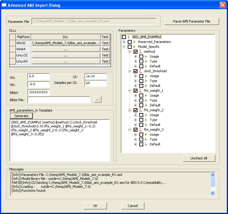
Select the library file, and click Open. On the Import AMI Dialog, click the Advanced button to open the Advanced AMI Import Dialog:
Click on the Parameters tree to expand the elements:
The Parameters tree is populated from the parameters file. Reserved parameters are marked R and Input parameters are marked I. Reserved and Input parameters are added as component properties when the component is created. By default, only the Model Specific parameters are checked. Use the checkboxes to select Resrerved parameters or to uncheck Model Specific parameters. Selected parameters appear in the Netlist Parameter string. Click the Generate button to create the netlist parameter string. Here is an example of the Advanced AMI Import dialog with all the steps completed:.
Click OK to return to the Import AMI Dialog:
Click Import to create the AMI component. Designer notifies you that the component has been created:
You can verify that the component is in the Project tree:
You can rename the component as desired. To place the component in the schematic, select it in the Components list, drag it into the schematic, and press ENTER to place the component.
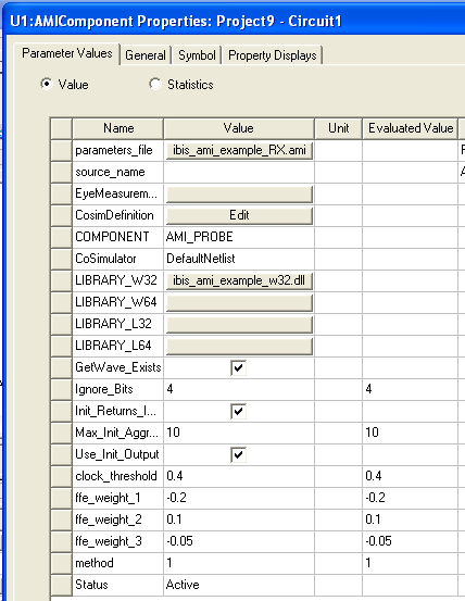
Click on the component and display the Properties:
The properties include the selected parameters from the file. In addition to the reserved and model-specific parameters from the file, Nexxim adds parameters to the driver and receiver components. For the reveiver (RX) component shown above, the only built-in parameter is the source_name property. This is the name of the AMI driver (TX) for this receiver. The available sources will be listed in a pulldown menu. The added built-in properties for an AMI driver (TX) are described below. Click on the AMI Source to display the Properties window:
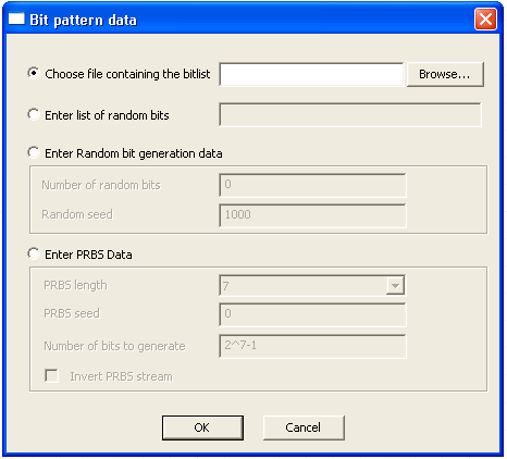
Set up the AMI source properties: • The probe_name property identifying the AMI Probe that is the primary receiver on the channel with this source (other AMI Sources and AMI Probes in the circuit represent crosstalk to this channel). • The logic low, vlow. The default is 0 volt. • The logic high, vhigh. The default is 1 volt. • The risetime of input (vrise). The default is 5.0e-10 seconds (500 picoseconds). • The falltime of input (tfall). The default is 5.0e-10 seconds (500 picoseconds). • The phase_delay for this source. The default is 0 seconds. • The data rate: Use the UIorBPS pulldown to select UnitInterval or BitsPerSecond. Then use the UIorBPSValue field to enter the unit interval size or number of bits per second. • The duty cycle distortion (dcd), as a fraction of UI between 0 and 1. The default is 0. • The standard deviation for the Gaussian distribution of random jitter (txrj). The default is 0 seconds. • The amplitude for the Periodic random jitter (txpj). The default is 0 seconds. • The amplitude for the Uniform random jitter (txuj). The default is 0 seconds. • The number of unit intervals to be used in computing the step response (step_resp_num_ui). The default is 100. • Click on the Bit Pattern button to open the dialog:
Select one of these methods for generating the AMI bit pattern. To link to a file with the bit values, click on the Choose file button, then use the Browse dialog to locate and select the data file. To specify a bitlist, click the Enter list button and type in the list of 1s and 0s. To generate a random sequence of bits (instead of the bitlist or bitfile), click the Enter random button. Enter the number of bits and the seed value. To generate a pseudorandom sequence of bit patterns of various lengths, click the Enter PRBS Data button. Use the pulldown to select the length of the pattern, PRBS_length, (2 to 31 bits). Enter a PRBS seed value, and specify the total number of bits to be generated. To invert the PRBS bit stream, check the checkbox at the lower left of the PRBS Data panel. Click OK to close the Bit pattern dialog and return to the AMI Source parameter list.. • To specify one or more repeats of the bits in the bitlist, bitfile, random sequence, or PRBS, set the repeat_count parameter on the AMI Source to the number of repeats. • The do_encoding parameter controls 8b10b encoding of the transmitted bitstream. The default is no encoding (do_encoding=0). To enable 8b10b encoding, set do_encoding to 1. • The Hold Last Bit checkbox is for crosstalk analysis. When an aggressor’s bit stream is shorter than the victim’s bitstream, the aggressor’s bitlist can be repeated or the last bit value can be held for the duration of the victim’s bitstream. The default is to repeat (checkbox not checked).
HFSS视频教程 ADS视频教程 CST视频教程 Ansoft Designer 中文教程 |
|
Copyright © 2006 - 2013 微波EDA网, All Rights Reserved 业务联系:mweda@163.com |
|