|
微波射频仿真设计 |
|
|
微波射频仿真设计 |
|
| 首页 >> Ansoft Designer >> Ansoft Designer在线帮助文档 |
|
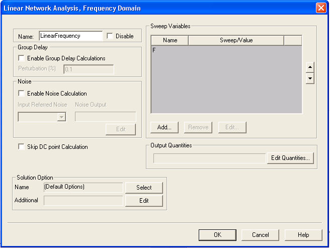
Nexxim Simulator > Running LNA from the Schematic EditorFrom the Schematic Editor, perform the following steps to set up a Nexxim linear network analysis, and run the analysis. 1. Right-click on the Analysis menu in the Project window to open a menu. 2. Select Add Nexxim Solution Setup from the menu, then slide the cursor to select Linear Network Analysis from the subordinate menu. The Linear Network Analysis, Frequency Domain dialog box appears.
3. Type an Analysis Name (or accept the default name, for example “LinearFrequency”). 4. For most simulations, leave the Disable box unselected (the default setting). Selecting this box lets you store multiple solution setups for later use. (Note that if a solution setup is disabled before the analysis is run, any changes made to the design will invalidate the simulation results.) 5. Depending on the requirements of the project, you can select Enable Group Delay Calculations and specify a Perturbation as a percentage of the test frequency. (see Group Delay Analysis later in this topic). 6. Depending on the requirements of the project, you can select Enable Noise Calculation. When the Enable Noise Calculation box is checked, the Noise Output field is activated. When at least one Noise Output has been added, the Input Referred Noise field is activated. a. Click the Edit button below the Noise Output field to open a Noise Output dialog. Select one or more currents through devices or voltages through nets, and then click OK to close the Noise Output dialog (or click Cancel to close the dialog without selecting any outputs). b. After adding one or more Noise Output elements, select a source for the input-referred noise calculation from the list in the Input Referred Noise pulldown. See the LNA Technical Notes for more information on LNA noise calculations. 7. By default, the field solvers solve for the DC frequency. To disable the DC calculation, check Skip DC Point Calculation.The results without the DC calculation are reliable only for circuits with linear devices and no non-zero-valued sources (AC sources are OK). 8. To add a basic frequency sweep, locate the Sweep Variable area in the Linear Network Analysis, Frequency Domain dialog box. a. In the Sweep Variable area, select the frequency F, then click Edit. The Add/Edit Sweep dialog box appears. b. In the Variable list, frequency F is selected (and cannot be changed). Select one of the following: Single value, Linear step, Linear count, Decade count, or Octave count. c. Type the sweep values into the Value text box (for Single value), or into the Start, Stop, and Step text boxes (for Linear, Decade, or Octave count), and make sure that the appropriate units (GHz, MHz, kHz) are selected for each. d. Click Add, and then click OK to close the Add/Edit Sweep dialog box. e. The Linear Network Analysis, Frequency Domain dialog box reappears. f. For more information, see Variable Sweep. 9. Click on the Edit Quantities button in the Output Quantities field to open the Output Quantities dialog box. Select and Add the outputs to be analyzed, then click OK to return to the Linear Network Analysis, Frequency Domain dialog box.
10. Optionally, use the fields in the Solution Option panel to select or add DC analysis options and other Nexxim options to the design. • Click the Select button on the Name field to open the Select Solution Options dialog. If any options sets have been defined, their names appear in the Select Solution Options list. To select a named option set that you have previously defined, click the name of the option set, then click OK to return to the LNA Analysis dialog. The named option set appears in the Name field in the Solution Options panel. See Analysis-Specific Options for details on creating option sets outside of the Solution Setup dialog. To create a new option set, click New. The Solution Options dialog box appears. Use the Name field to name the new option set. Select the DC Options tab. Make the appropriate changes to option values, then click OK to return to the Select Solutions dialog box. On the Select Solutions dialog, click the name of the new option settings, then click OK to return to the DC Analysis dialog. The name of the new option settings appears in the Name field in the Solution Options panel. • Click the Edit button on the Additional field to open a text-entry dialog, Edit additional options. Use the text box to enter any Nexxim options exactly as they are to appear in the netlist. Do not include the keyword .OPTIONS; the .OPTIONS keyword is automatically inserted at the beginning of the line in the netlist statement. The line can contain multiple options settings. Use spaces to separate the options settings. To modify or delete an option once it has been added, just edit or delete its entry in the list. To clear all options, delete the entire line. Click OK to return to the Linear Network Analysis, Frequency Domain dialog. The options in the Additional field are automatically added to the netlist when the solution containing them is performed. g. For more information, see DC Analysis Options. 11. Click Finish to close the Linear Network Analysis, Frequency Domain dialog box. 12. Run the simulation: • On the Circuit menu, click Analyze. If the circuit is set up correctly, the analysis begins immediately and a red progress bar appears. • The Message Window signals succes or failure. • For details on creating and modifying reports, see Generating Reports and Postprocessing.
HFSS视频教程 ADS视频教程 CST视频教程 Ansoft Designer 中文教程 |
|
Copyright © 2006 - 2013 微波EDA网, All Rights Reserved 业务联系:mweda@163.com |
|