|
微波射频仿真设计 |
|
|
微波射频仿真设计 |
|
| 首页 >> Ansoft Designer >> Ansoft Designer在线帮助文档 |
|
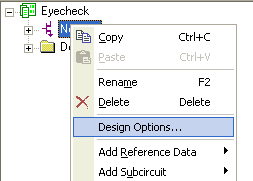
Nexxim Simulator > Design-Level OptionsTo set option defaults that affect a particular design, select the design in the Project tree, and then select Design Options from the right-click menu:
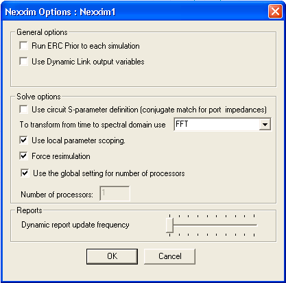
The Nexxim Options dialog box opens. .
General Options Run ERC Prior to each simulation runs electrical rules checking for nets or nodes that are electrically connected but not physically connected. The ERC results display in the message window. The simulation proceeds regardless of the results of ERC. Use Dynamic Link output variables enables the Nexxim simulation to use output variables from dynamically-linked HFSS designs. Using the HFSS output variables gives Nexxim access to nearly all types of HFSS data instead of just S-parameters. However, accessing the HFSS output variables can slow down the analysis. See Access to HFSS Output Variables from Designer and Nexxim for details. Solve Options Use circuit S-parameter definition... controls the definition for port impedances. For Nexxim, this option should typically be selected (checkbox checked). The definition of a “matched port” depends on the application. In applications that deal mostly with circuit quantities (including the Nexxim and System simulators), a “matched port” has a characteristic impedance that maximizes the power transfer. This is also called a “conjugate match.” In applications that deal mostly with electromagnetic quantities (including HFSS and Planar EM), a “matched port” has a characteristic impedance that maximizes the transfer of the voltage wave. The two definitions differ only by the conjugate of the characteristic impedance of the port. For real port impedances, there is no difference. To transform from time to spectral domain... allows you to select the method used to transform from the time domain to the spectral domain for the selected netlist design. The default method, Fourier Integration, is very accurate but may be time-consuming for large data sets. The alternative method uses the Fast Fourier Transform to achieve faster conversion with a slight reduction in accuracy. Use local parameter scoping controls the precedence of parameter handling in subcircuits. By default, option PARHIER=local is inserted in the Nexxim netlist. Uncheck the box to restore global parameter scoping. See Overriding the Precedence of Subcircuit Parameters for details. Force resimulation sets Nexxim to resimulate a design for a calculation such as an optimization, discarding any existing data. Uncheck the box to set nexxim to perform any calculations on available data. This setting is useful, for example, when running optimizations on data generated by multiple sweeps. Use global setting for number of processors is enabled by default. Uncheck the box to enable the Number of processors field. Specify the number of separate processor threads to use for this project. Reports Options Dynamic report update frequency allows you to control the updates of reports as analyes complete. The default is maximum frequency. Reduce the frequency if desired to control the rate of redrawing.
HFSS视频教程 ADS视频教程 CST视频教程 Ansoft Designer 中文教程 |
|
Copyright © 2006 - 2013 微波EDA网, All Rights Reserved 业务联系:mweda@163.com |
|