|
微波射频仿真设计 |
|
|
微波射频仿真设计 |
|
| 首页 >> Ansoft Designer >> Ansoft Designer在线帮助文档 |
|
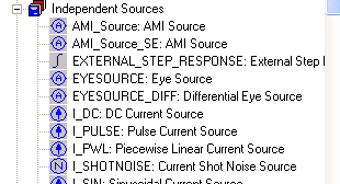
Nexxim Simulator > Add an Eye Source for VerifEyeTo run VerifEye analysis, the design must include one Eye Source and a corresponding Eye Probe. Select the Eye Source from the Independent Sources list on the Components tab:
Both single-ended and differential versions are available.
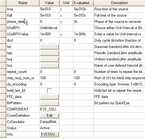
Click on the Eye Source to display the Properties list:
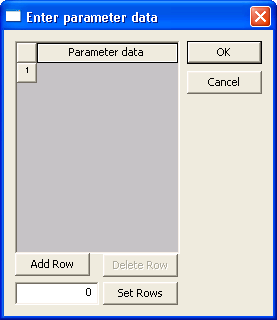
For VerifEye analysis, only the following Eye Source parameters apply: • The resistance to be placed in series with the eye source. The default is 50 Ohm. • The logic “low,” vlow. The default is 0 volt. • The logic “high,” vhigh. The default is 1 volt. • The risetime of input (trise). The default is 5.0e-10 seconds (500 picoseconds). • The falltime of input (tfall). The default is 5.0e-10 seconds (500 picoseconds). • The phase_delay for this source. The default is 0 seconds. • The data rate: Use the UIorBPS pulldown to select UnitInterval or BitsPerSecond. Then use the UIorBPSValue field to enter the unit interval size or number of bits per second. • The duty cycle distortion (dcd) value is a fraction of UI between 0 and 1. The default is 0. For txrj, txpj, and txuj, clicking the Value button allows you to specify one or more values, generating multiple jitter sources:
• For the random transmit jitter (txrj) the value is the standard deviation for the Gaussian distribution. The default is 0 seconds. • For the Periodic random transmit jitter (txpj) the value is the amplitude. Default: 0 seconds. • For the Uniform random transmit jitter (txuj) the value is the amplitude. Default is 0 seconds. • For the User-defined transmit jitter (txcj) the value is the name of the file containing the time (seconds) and probability density function (PDF) values. There is no default.
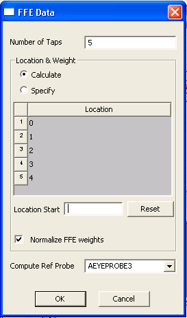
• The do_encoding parameter controls encoding of the transmitted bitstream. The default is no encoding (do_encoding=0). To enable 8b10b encoding, set do_encoding to 1. To enable the more modern 64b66b encoding, set do_encoding to 2. • To apply Feed-Forward Equalization, click on the FFE_data button and open the dialog:
• To enable Feed-Forward Equalization, set the Number of taps in the FFE field to a positive, non-zero value. The default is zero taps (no FFE). When one or more taps have been specified, the list of tap numbers and locations appears. • By default, Tap 1 is at location 0, the current UI. Use Location Start to set Tap 1 to a positive or negative location. Taps at positive locations are postcursors. Taps at negative locations are precursors. The location of the taps in the display change to reflect the selected starting location. (Click the Reset button to restore the default starting location.)
• To specify the tap weights, select Specify and enter the weights. The default is to have Nexxim calculate the weights. The algorithm always places the largest tap weight at location 0. • By default, normalization is performed such that the sum of the absolute values of all the weights is equal to one. Optionally, uncheck the Normalize FFE weights checkbox to disable normalization. • Use the pulldown to select a Compute Ref Probe. When FFE has been enabled, this field is required. A channel can have multiple probes, but only the probe actually at the receiver should be the reference probe. • For more information on FFE, see Feed-Forward Equalization. • Click OK to close the FFE_data dialog and return to the Properties window. • Click OK to close the Properties window.
HFSS视频教程 ADS视频教程 CST视频教程 Ansoft Designer 中文教程 |
|
Copyright © 2006 - 2013 微波EDA网, All Rights Reserved 业务联系:mweda@163.com |
|