|
微波射频仿真设计 |
|
|
微波射频仿真设计 |
|
| 首页 >> Ansoft Designer >> Ansoft Designer在线帮助文档 |
|
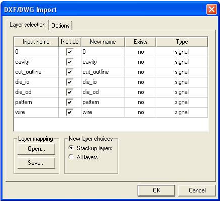
Importing and Exporting Data > Importing DXF and DWG Format FilesSee the introductory topic Importing 2D Model Files into the Layout Editor for the initial steps in the process of importing 2D data into the Layout Editor. The process for importing DXF and DWG format files into an active Layout Editor design uses a dialog box with two tabs. After you select a 2D model file to import, the following dialog opens:
• The Input name column shows the name of the layer in the DXF/DWG file (not editable). • Use the Include check boxes to specify which layers to import from the selected file. • Use the New name column to choose the destination layer for the objects on this input layer. • Click in the column to see a pulldown list of choices of existing layout layers, along with a new layer that has the name of the input layer. • Exists shows whether the layer already exists in the stackup in the current design (not editable). • Type identifies the layer type that will be used to place each layer in the file (not editable if the layer already exists; for layers that don’t exist, click in the column to see a pulldown list of choices). • Layer mapping allows you to Open and Save layer-mapping files. Create a layer-mapping file based on the layers marked to be imported. For details see Layer Mapping Files. • New layer choices controls the layout layer choices that appear in the New name pulldown list.
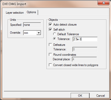
Next, click the Options tab:
• Use the Units pane and the Override pulldown to select the units to be used to interpret the DXF/DWG file contents. The Specified field shows the units used in the file. The Override units will be used when reading the file. The Override control defaults to the current Designer default units. Note that the final units on the imported layout will be the Designer default units set at the time of the import; if these units are different from the Override units, the imported units are converted. To set the Designer default units, see Default Units Tab. • Use the check boxes to fine-tune the import: — Auto detect closure causes polylines to be checked to see whether or not they are closed. If a polyline is closed, Designer creates a polygon in the design. — Self stitch causes multiple straight line segments to be joined to form polylines. Tolerance is used to decide if two coordinates are the "same" and should be considered for joining. If the resulting polyline is closed, a polygon is created in Designer. You have the choice of two different tolerances for self stitching: Default Tolerance and explicit Tolerance. Default tolerance is a geometric tolerance based on the extents of the project being imported. Explicit tolerance allows you to expand the tolerance based on your knowledge of the dxf project being imported. — Defeature removes certain small features in the imported geometry to reduce complexity. The features that are removed include multiple points placed within the specified distance, thin or narrow regions (“thins” and “spikes”), and extraneous points along straight line segments. Specify the distance in the Tolerance box. — Round coordinates rounds all imported data to the specified number of decimal points. — Convert closed wide lines to polygons imports wide polylines as polygons. You have more flexibility to change the shape of such an object when it is imported as a polygon.
When you have completed selections on both tabs, click OK on either tab and the file is imported into the active Layout window.
The following DXF entities can be imported as 2 dimensional objects from AutoCAD: • Arc • Solid • Circle • Block • Ellipse • Array of blocks (MInsert) • 2D Polyline, Polyline, and Line
HFSS视频教程 ADS视频教程 CST视频教程 Ansoft Designer 中文教程 |
|
Copyright © 2006 - 2013 微波EDA网, All Rights Reserved 业务联系:mweda@163.com |
|