|
微波射频仿真设计 |
|
|
微波射频仿真设计 |
|
| 首页 >> Ansoft Designer >> Ansoft Designer在线帮助文档 |
|
Dynamic Links and Solver On Demand > Pushing Excitations to an HFSS, Q3D, or SIwave Dynamic Link ModelThe procedures for pushing excitations to dynamically-linked HFSS, Q3D, and SIwave models are all very similar. You must first set up the field solver element so that the fields and currents are saved during simulations (refer to the HFSS, Q3D, or SIwave documentation). After simulating the circuit/field-solver combination, you can right click on the field solver element in the schematic editor and choose which solution and frequency to use to populate the field solver excitation values. 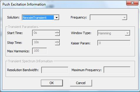
• The Resolution Bandwidth and Maximum Frequency of the data (that will be sent or “pushed” to the dynamically linked project) are calculated based on the transient parameter settings: Start Time, Stop Time, and Max Harmonics. The start and stop times must lie within the transient simulation time limits. • Window Type is described in Plotting Spectral Domain Data. The coherent gain is always adjusted to account for the processing loss of the window when pushing excitations to dynamically linked projects. • No Frequency validation is performed, so you can push a set of excitation values from a parent circuit at one frequency into an HFSS model simulated at another frequency.
Notes 1. The most common reason Push Excitations fails is that one or more terminals of the dynamically linked model are left unconnected. Nexxim does not compute voltages on unconnected terminals so no excitations can be determined. Adding short unconnected wires to the unconnected terminals of the model will cause Designer to assign unique net names to the terminals and allow Nexxim to compute voltages. Once Nexxim has computed voltages excitations can normally be pushed to the dynamically linked design. 2. Excitations cannot be pushed to HFSS, Q3D, or SIwave if parameter values are swept in the Designer setup.
HFSS视频教程 ADS视频教程 CST视频教程 Ansoft Designer 中文教程 |
|
Copyright © 2006 - 2013 微波EDA网, All Rights Reserved 业务联系:mweda@163.com |
|


