|
微波射频仿真设计 |
|
|
微波射频仿真设计 |
|
| 首页 >> Ansoft Designer >> Ansoft Designer在线帮助文档 |
|
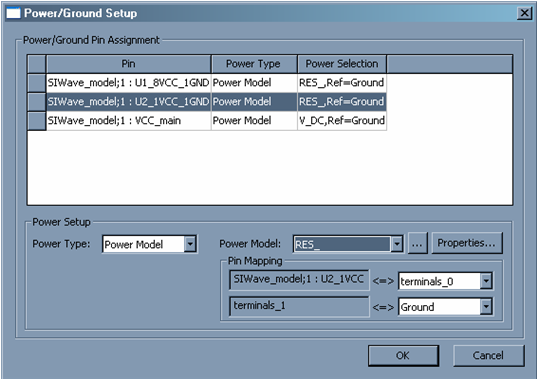
Schematic Editor > Power/Ground Pin SetupTo configure Power and Ground settings, click Set as power/ground pins in the I/O Wizard Dialog; this opens the Power/Ground Setup dialog for the selected pins.
Fields in the main grid-display window are not editable, but instead show the status of what you configure using the Power Setup fields at the bottom of the dialog. You can select multiple rows and use the Power Setup fields to make multiple changes to many pins simultaneously. • Power Type can either be “Buffer Connection”, “Reference Pin”, or “Power Model”. — Buffer Connection means the pin will be directly connected to the Pull Up or Pull Down, according to what was specified in the Signal Setup dialog. — Reference Pin does not specifically assign a Power source or Ground, but this setting can be used for pin mapping. — Power Model allows a one or two port component to be connected directly to the pin. The browse button (…) allows you to load a model. If the component selected for the Power Model has two pins, the Pin Mapping area is displayed. The top Pin Mapping box chooses which of the Power Model’s terminals is directly connected to the Power Pin selected in the pin grid. The bottom Pin Mapping box allows you to assign the remaining Power Model terminal to a net. • Clicking Properties allows you to customize the parameters for the selected Power Model component. • In order to connect a ground terminal, select Power Type: Power Model, then use the browse button ( ... ) to load a RES_ component as the Power Model. This two port component, when not configured with a resistance parameter, will act as a short. The pin mapping for the RES_ Power Component allows you to then short the Power pin to Ground.
Click OK to close the dialog and implement any changes that have been configured.
HFSS视频教程 ADS视频教程 CST视频教程 Ansoft Designer 中文教程 |
|
Copyright © 2006 - 2013 微波EDA网, All Rights Reserved 业务联系:mweda@163.com |
|