|
微波射频仿真设计 |
|
|
微波射频仿真设计 |
|
| 首页 >> Ansoft Designer >> Ansoft Designer在线帮助文档 |
|
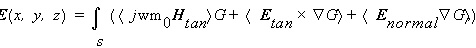
HFSS and Planar EM Simulators > Radiated FieldsWhen calculating radiation fields, the values of the currents on the structure are used to compute the fields in the space surrounding the device. This space is typically split into two regions — the near-field region and the far-field region. The near-field region is the region closest to the source. In general, the electric field E(x,y,z) external to the region bounded by a closed surface may be written as:
where: • s represents the radiation surfaces. • j
is the imaginary unit, • w is the angular frequency, 2pf. • m0 is the relative permeability
of the free space. • Htan is the component of the
magnetic field that is tangential to the surface. • Enormal
is the component of the electric field that is normal to
the surface. • Etan is the component of the
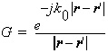
electric field that is tangential to the surface. • G is the free space Green’s function, given by
where: • k0 is the free space wave
number, • r and r1 represent, respectively, field points and source points on the surface.
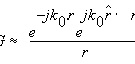
In the far field where r>>r' (and usually r>>l0), Green’s function can be approximated as
When this form of G is used in the far-field calculations, the fields that result have an r dependence in the form of
This r dependence is characteristic of a spherical wave, which is a key feature of far fields. The far field is a spherical TEM wave with the following equation:
where h0 is the intrinsic impedance of free space.
• When Designer calculates near fields, the general near-field expressions discussed at top are used. • When Designer calculates far fields, the far-field approximations discussed above are used, and the result is valid only for field points in the far-field region. The far-field phase reference is centered on the x-y extents of the structure at the top of the dielectric stack up.
The topics for this section include:
HFSS视频教程 ADS视频教程 CST视频教程 Ansoft Designer 中文教程 |
|
Copyright © 2006 - 2013 微波EDA网, All Rights Reserved 业务联系:mweda@163.com |
|
 .
.
 .
.