淘宝官方店     推荐课程     在线工具     联系方式     关于我们  


微波射频仿真设计   Ansoft Designer 中文培训教程   |   HFSS视频培训教程套装


Agilent ADS 视频培训教程   |   CST微波工作室视频教程   |   AWR Microwave Office

          首页 >> Ansoft Designer >> Ansoft Designer在线帮助文档


Ansoft Designer / Ansys Designer 在线帮助文档:


Nexxim Simulator >
Nexxim Component Models >
Microstrip Elements >
   Lange Coupler, Electrical Length       

Lange Coupler, Electrical Length


[spacer]


[spacer]

Netlist Format

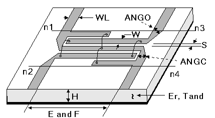
A Lange coupler, physical length instance has the following netlist format:

ALANGExxx n1 n2 n3 n4 N=4 W=val S=val E=val F=val
NW=val DW=val SW=val WL=val ANGC=val ANGO=val
COMPONENT=mslange_electrical SUBSTRATE=substrate_name

n1, n2, n3, and n4 are the names of the nodes attached to the coupler. The entry COMPONENT=mslange_electrical identifies the element.

The entry SUBSTRATE=substrate_name identifies the microstrip substrate model name selected for the design (see Selecting a Microstrip Substrate). See the Microstrip (MS) Substrate for information on this substrate type.


Lange Coupler, Electrical Length Instance Parameters

Parameter

Description

Unit

Default

N

Number of lines. Must be 4.

None

4

W

Conductor width

Meter

1e-3

S

Conductor spacing

Meter

1e-3

E

Electrical length

Degree

10e-3

F

Reference frequency for E

Hertz

1e9

NW

Number of bond wires

None

1

DW

Diameter of bind wires

Meter

25.4e-6

SW

Spacing between bond wires

Meter

0.0

WL

Width of connecting lines

Meter

1e-3

ANGC

Miter angle of center arm bends

Degree

45

ANGO

Miter angle of outer arm bends

Degree

45


Netlist Example

ALANG1 Port1 Port2 Port3 Port4 N=4 W=1e-3 S=0.2e-3 F=2.5e9
+ COMPONENT=mslange_electrical SUBSTRATE=FR4

where FR4, the selected layout technology or substrate type, has a definition such as:

.SUB FR4 MS( H=7.6200e-004 Er=4.4 TAND=0.02 TANM=0
+ MSat=0 MRem=0 HU=0.00508 MET1=1.72413793103448
+ T1=1.7145e-005 RGH=0mil)

Notes

1. The bond wire is considered to be a semicircular shape with diameter equal to the separation between the end points..

2. Taking port 1 to be defined between node 1 and ground (node 0), the remaining ports are defined between the following nodes:
Coupled port: Node n2 and GND
Isolated port: Node n3 and GND
Through port: Node n4 and GND


HFSS视频教学培训教程 ADS2011视频培训教程 CST微波工作室教程 Ansoft Designer 教程

                HFSS视频教程                                      ADS视频教程                               CST视频教程                           Ansoft Designer 中文教程


      Copyright © 2006 - 2013   微波EDA网, All Rights Reserved    业务联系:mweda@163.com