|
微波射频仿真设计 |
|
|
微波射频仿真设计 |
|
| 首页 >> Ansoft Designer >> Ansoft Designer在线帮助文档 |
|
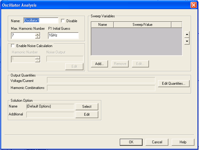
Nexxim Simulator > Running Single-Tone Oscillator Analysis from the Schematic EditorSingle-tone oscillator analysis is typically used on a circuit that contains an oscillator source of unknown frequency, with no other frequency sources in the circuit. From the Schematic Editor, perform the following steps to set up and run a single-tone oscillator analysis using Nexxim. 1. Set up the schematic circuit for oscillator analysis by inserting an oscillator probe between two nodes in your circuit. Edit the probe properties and specify an initial guess for the unknown oscillating frequency (FREQ parameter) and an initial voltage (A parameter). See Using the Oscillator Probe for more information. 2. Right-click on the Analysis menu in the Project window to open a menu. 3. Select Add Nexxim Solution Setup from the menu, then slide the cursor to select Oscillator Analysis (1-Tone) from the subordinate menu. The Oscillator Analysis dialog box appears.
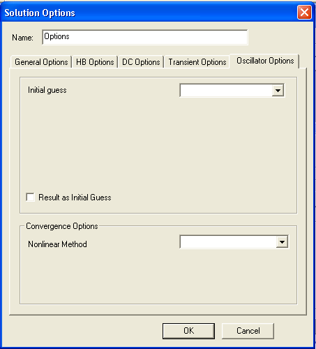
4. Type an Analysis Name (or accept the default name, for example, “Oscillator”). 5. For most simulations, leave the Disable box unselected (the default setting). Selecting this box lets you store multiple solution setups for later use. (Note that if a solution setup is disabled before the analysis is run, any changes made to the design will invalidate the simulation results.) 6. The Oscillator Analysis dialog box appears. This dialog allows you to specify the maximum harmonic number to include in the analysis, and a frequency in Hz to be used as the initial guess for the oscillator frequency: • Specify the maximum harmonic number to use in the analysis by clicking the up and down arrows in the Max. Harmonic Numberfield. • Specify the frequency for F1 Initial Guess. The initial guess should be the same frequency as the FREQ parameter on the oscillator probe. The F1 Initial Guess value overrides the probe FREQ parameter if they are not the same. 7. Optional: To run Phase Noise analysis, check the Enable Noise Calculation box. See Running Phase Noise Analysis from the Schematic Editor for details on the other steps in setting up the phase noise analysis. 8. To add a sweep, locate the Sweep Variable area in the Oscillator Analysis dialog box. • In the Sweep Variable area, click Add, and the Add/Edit Sweep dialog box appears. • In the Variable list, select Temp or the name of a variable (when a variable has been defined for the design), and then select one of the following: Single value, Linear step, Linear count, Decade count, or Octave count. • Type the sweep values into the Value text box (for Single value), or into the Start, Stop, and Step text boxes (for Linear, Decade, or Octave count), and make sure that the appropriate units are selected for each. • For details on sweeps, see Variable Sweep. • Click Add, and then click OK to close the Add/Edit Sweep dialog box. • The Oscillator Analysis dialog box reappears. 9. Click on the Edit Quantities button in the Output Quantities field to open the Defined Output Quantities dialog box. Expand the icons for the circuit components (Nets and individual devices), and use the checkboxes to select quantities for output. Expand the Harmonics icon to display a list of harmonics (the number of available harmonics is set by the Max Harmonic Number specified in Step 6). Select and Add the harmonics you want to analyze. If you do not select any harmonics, harmonics DC, F1, 2F1, 3F, and 4F1 are automatically selected. In the Report dialog, only selected harmonics are available for plotting. Click OK to return to the Oscillator Solution Setup dialog box. 10. Optionally, use the fields in the Solution Option panel to select or add Oscillator analysis options and other Nexxim options to the design. • Click the Select button on the Name field to open the Select Solution Options dialog. If any options sets have been defined, their names appear in the Select Solution Options list. To select a named option set that you have previously defined, click the name of the option set, then click OK to return to the Oscillator Analysis dialog. The named option set appears in the Name field in the Solution Options panel. See Analysis-Specific Options for details on creating option sets outside of the Solution Setup dialog. To create a new option set, click New. The Solution Options dialog box appears. • Select the Oscillator Options tab:
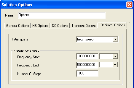
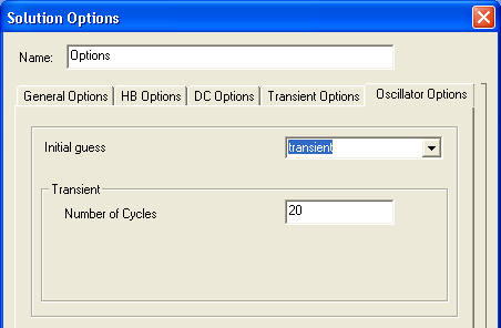
• Enter a name for the options, or accept the default name. • To select an Initial Guess option, click in the pulldown field. The options are Frequency Sweep, Transient, and DC. For an Initial Guess of Frequency Sweep, the dialog changes to:
Enter the Frequency Start and Frequency End values. Use the pulldown at the right of the value to select the unit (Hz or kHz). For an Initial Guess of Transient, the dialog changes to:
Enter a Number of Cycles if the default
is not as desired. • Click the Result as Initial Guess box to use the result from the previous oscillator sweep step as the initial guess for the current step. Use of this setting can avoid repeated analysis runs. • To select a Convergence Option, click in the pulldown field. The options are Newton, Descent, and Damped Newton. • Make the appropriate changes to option values, then click OK to return to the Select Solutions dialog box. On the Select Solutions dialog, click the name of the new option settings, then click OK to return to the DC Analysis dialog. The name of the new option settings appears in the Name field in the Solution Options panel. • Click the Edit button on the Additional field to open a text-entry dialog, Edit additional options. Use the text box to enter any Nexxim options exactly as they are to appear in the netlist. Do not include the keyword .OPTIONS; the .OPTIONS keyword is automatically inserted at the beginning of the line in the netlist statement. The line can contain multiple options settings. Use spaces to separate the options settings. To modify or delete an option once it has been added, just edit or delete its entry in the list. To clear all options, delete the entire line. Click OK to return to the Oscillator Analysis dialog. The options in the Additional field are automatically added to the netlist when the solution containing them is performed. • For more information on the option settings, see Oscillator Analysis Options. 11. When all setup steps are as desired, click Finish on the Oscillator Analysis dialog. The solution setup is added to the Project tree under the Analysis icon. 12. Run the simulation: • Click on the solution setup in the Project tree and click Analyze from the menu. If the circuit is set up correctly, the analysis begins immediately and a red progress bar appears. • If the analysis is not successful, an error message appears in the Message Window. Check the Message Window for an explanation, and then take corrective action. 13. View results: • After a successful oscillator analysis, Nexxim displays a message like the following in the Message Window, near the end of the messages: [info]analysis:osc(status): The frequency value will be the one calculated for your circuit, and the time and date will show the time of the analysis on your machine.
HFSS视频教程 ADS视频教程 CST视频教程 Ansoft Designer 中文教程 |
|
Copyright © 2006 - 2013 微波EDA网, All Rights Reserved 业务联系:mweda@163.com |
|