|
微波射频仿真设计 |
|
|
微波射频仿真设计 |
|
| 首页 >> Ansoft Designer >> Ansoft Designer在线帮助文档 |
|
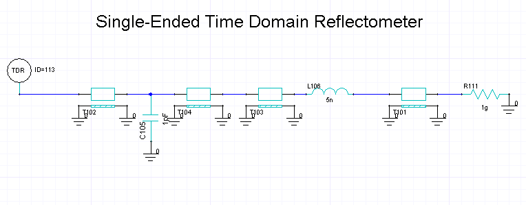
Nexxim Design Examples > Single-Ended TDRThe schematics for both single-ended and differential TDRs are in one project in the Examples directory. Open the TDR Schematic project from its file in the Examples directory. 1. On the File menu, select Open Examples. The File Open window appears. 2. Open SI_Circuit, then select the file TDR_Example.adsn. Click Open. Expand the TDR_Example icon and the Single Ended icon. The single-ended TDR schematic appears in the design window:
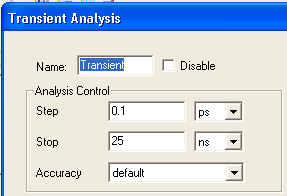
The single-ended TDR consists of a unit pulse source, a 50-ohm reference impedance, a reference length of transmission line (50 ohm impedance, 0.5ns delay), and two voltage probes, Vexcited_pos for the step voltage and Vdetected_pos for the reflected voltage. The Device Under Test (DUT) is a series of transmission lines and discrete passives to represent the typical TDR problem of finding where impedance changes in a line. In sequence, the DUT elements are: • Transmission line, 50-ohm impedance, 1ns delay. • Shunt capacitor, 1pf. • Transmission line, 50-ohm impedance, 3ns delay. • Transmission line, 55-ohm impedance, 5ns delay. • Series inductor, 5nH. • Series resistor, 1gigohm. • Terminating ground. 3. Expand the Analysis icon and double-click on the Transient analysis setup.
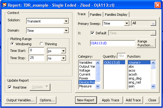
4. Left-click on the Transient analysis icon and select Analyze. The analysis runs to completion. 5. Expand the Reports icon and right-click on the Zload report setup. Select Modify Report to open the Report Setup.
6. Click New Report to generate the report:
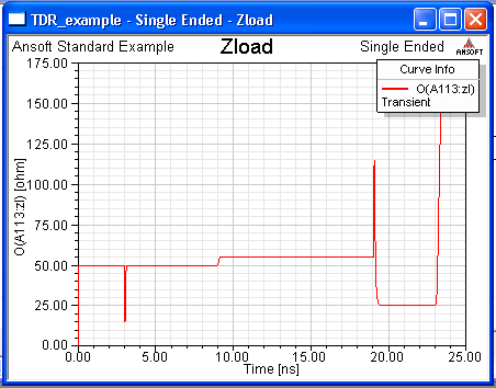
The TDR analysis allows us to identify each of the components of the DUT by their timing and behavior. • At 3ns, the impedance drops to indicate the presence of the capacitor. The 3ns delay is the TDR internal delay (0.5ns) plus the first transmission line delay (1ns), times two for the reflection. Both transmission lines are at 50 ohms. • At 9ns, the impedance increases to 55 ohm at the beginning of the 55-ohm line segment. 9ns=2(0.5+1.0+3.0). • At 19ns, the impedance jumps to indicate the presence of the inductor, then immediately drops to25 ohm for the resistor. 19ns=2((0.5+1.0+3.0+5.0). • At 23ns, the impedance goes to infinity
at the high final resistor.
HFSS视频教程 ADS视频教程 CST视频教程 Ansoft Designer 中文教程 |
|
Copyright © 2006 - 2013 微波EDA网, All Rights Reserved 业务联系:mweda@163.com |
|