|
微波射频仿真设计 |
|
|
微波射频仿真设计 |
|
| 首页 >> Ansoft Designer >> Ansoft Designer在线帮助文档 |
|
Nexxim Design Examples > Differential TDRExpand the TDR_Example icon and the Differential icon. The differential TDR schematic appears in the design window:
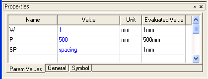
The differential TDR consists of two channels, each with a unit pulse source, a 50-ohm reference impedance, a reference length of transmission line (50 ohm impedance, 0.5ns delay), and two voltage probes, Vexcited_pos or Vexcited_neg for the step voltage and Vdetected_pos or Vdetected_neg for the reflected voltage. The Device Under Test (DUT) is microstrip coupled line pair and a termination network. The transient analysis sweeps the spacing between the coupled lines, so that we can how thae spacing affects the differential impedance, Zdiff. 7. Select the coupled lines. The Property window shows that the spacing parameter SP has been defined with a local variable.
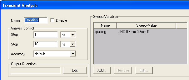
8. Expand the Analysis icon, double-click on the Transient analysis setup, and verify the sweep of the spacing variable.
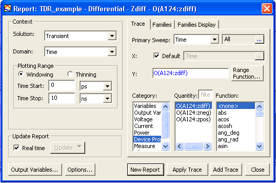
9. Left-click on the Transient analysis icon and select Analyze. The analysis runs to completion. 10. Expand the Reports icon and right-click on the Zdiff report setup. Select Modify Report to open the Report Setup.
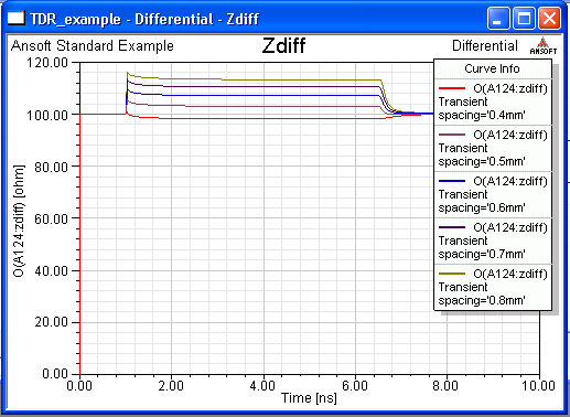
11. Click New Report to generate the report:
The TDR analysis shows how the spacing affects the differential impedance.
HFSS视频教程 ADS视频教程 CST视频教程 Ansoft Designer 中文教程 |
|
Copyright © 2006 - 2013 微波EDA网, All Rights Reserved 业务联系:mweda@163.com |
|