|
微波射频仿真设计 |
|
|
微波射频仿真设计 |
|
| 首页 >> Ansoft Designer >> Ansoft Designer在线帮助文档 |
|
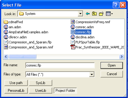
Getting Started with Ansoft Designer > Edit Amplifier2 PropertiesIn this example, we use an external data file, comrec.flp, to define the compression characteristics for the second and third amplifiers. This file is also used later to define the intermodulation table for the two mixers. 1. Double click the second amplifier, and the Properties dialog box appears.
2. In the File row, under Value, click the blank button. The Select File dialog box opens. 3. In the Select File dialog box, use the Look in field to browse to the directory where Designer is installed. Browse to Examples\System. Click on the file comrec.flp or type its name in the File Name field. 4. Click Open to close the Select File dialog box. The file comrec.flp appears as the value of the FILE property. 5. In the Properties dialog box for Amplifier2, set the values of the additional properties as shown. The local variable MID_GAIN is defined in the file comrec.flp. Leave all other values unchanged.
6. Click OK to close the Properties dialog box.
HFSS视频教程 ADS视频教程 CST视频教程 Ansoft Designer 中文教程 |
|
Copyright © 2006 - 2013 微波EDA网, All Rights Reserved 业务联系:mweda@163.com |
|